Modular electrical grid interface device

a technology of electrical grid and interface device, which is applied in the direction of instruments, process and machine control, analysing/displaying, etc., can solve the problems of inflexibility for integrating best of breed technologies, difficulty in deploying a mixed network of assets optimized for different situations, and high cost of current ami-based solutions

Inactive Publication Date: 2009-04-02
GRIDPOINT
View PDF32 Cites 512 Cited by
  • Summary
  • Abstract
  • Description
  • Claims
  • Application Information

AI Technical Summary

Benefits of technology

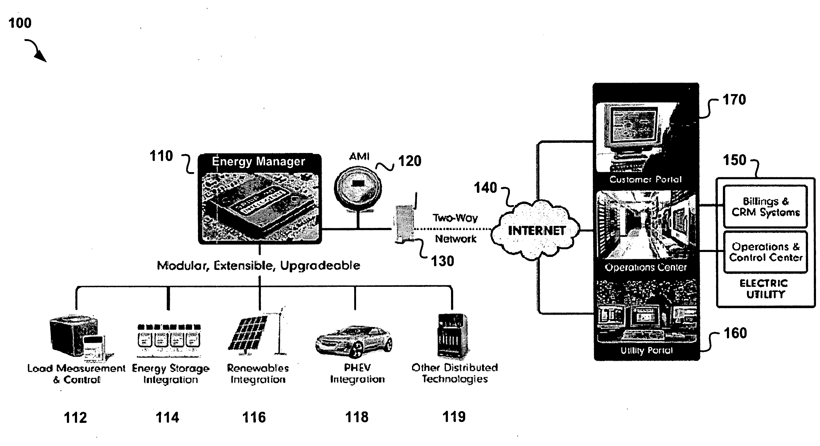
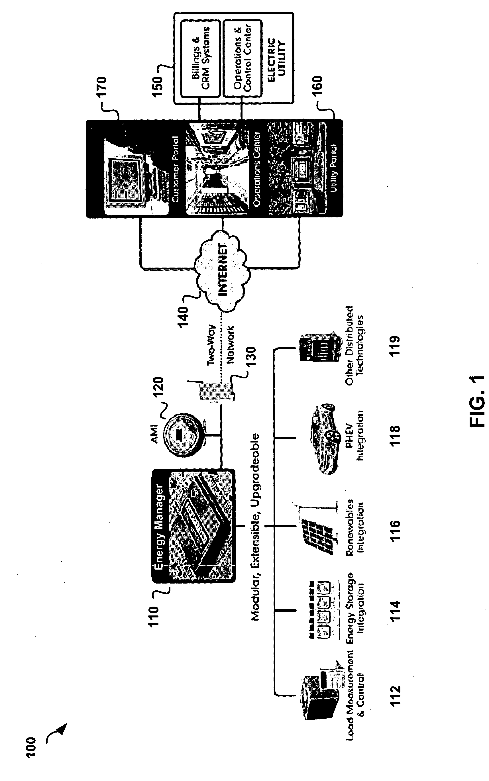
[0009]In another embodiment, the invention provides a smart grid management system that includes intelligent network asset control systems connected to a network, each controlling at least one asset on a power grid. A plurality of intelligent commercial building control systems are connected to the network, each controlling at least one commercial building device connected to the power grid. A plurality of intelligent residential control systems are provided, each controlling at least one residential device connected to the power grid. At least one utility operator console is connected to the network. The utility operator console is configured to control all of the intelligent control systems so as to enable a console operator to manage the supply of and demand for power on the power grid.

Problems solved by technology

However, instrumentation at the billing level is only a small part of a true smart grid solution.
There is no flexibility for integrating best of breed technologies and there are few standards for defining interoperability.
There is difficulty in deploying a mixed network of assets optimized for different situations.
Current AMI-based solutions are also expensive and hard to justify across all rate-payer segments.
A “one size fits all” approach does not work because of poor price equanimity.
Current AMI-based solutions do not adequately define peak load growth curtailment that benefits all rate payers.
In addition, modularity and expandability in current AMI-based solutions is severely limited.
Communications media will change within the asset life of the meter, thereby causing compatibility problems.

Method used


Image

  • Modular electrical grid interface device
  • Modular electrical grid interface device
  • Modular electrical grid interface device

Examples


Embodiment Construction

[0020]For the purposes of this disclosure, a computer readable medium stores computer data in machine readable form. By way of example, and not limitation, a computer readable medium can comprise computer storage media and communication media. Computer storage media includes volatile and non-volatile, removable and non-removable media implemented in any method or technology for storage of information such as computer-readable instructions, data structures, program modules or other data. Computer storage media includes, but is not limited to, RAM, ROM, EPROM, EEPROM, flash memory or other solid-state memory technology, CD-ROM, DVD, or other optical storage, magnetic cassettes, magnetic tape, magnetic disk storage or other mass storage devices, or any other medium which can be used to store the desired information and which can be accessed by the computer.

[0021]For the purposes of this disclosure a module is a software, hardware, or firmware (or combinations thereof) system, process o...


PUM


Abstract

A smart grid gateway which includes a onboard computer programmed to provide load measurement and control of at least one local resource or asset. At least one metrology module is configured to provide metering of the at least one local resource or asset. At least one LAN module is configured to communicate with the at least one local resource or asset. At least one WAN module is configured to communicate with a network operations center.

Description

[0001]This application claims priority to U.S. Provisional Patent Application No. 60 / 976,495 filed on Oct. 1, 2007, which is incorporated by reference in its entirety herein. The disclosure of U.S. patent application Ser. No. 12 / 210,761 filed on Sep. 15, 2008 is incorporated herein by reference in its entirety.[0002]This application includes material which is subject to copyright protection. The copyright owner has no objection to the facsimile reproduction by anyone of the patent disclosure, as it appears in the Patent and Trademark Office files or records, but otherwise reserves all copyright rights whatsoever.FIELD OF THE INVENTION[0003]The present invention relates in general to the field of electric power distribution, and in particular to methods and systems for electric power management.BACKGROUND OF THE INVENTION[0004]The Advanced Metering Infrastructure (AMI) system has been proposed for measuring energy usage using advanced devices such as water meters, electric meters and...

Claims


Application Information

Patent Timeline
Patent Type & Authority Applications(United States)
IPC IPC(8): G06F1/32G06F1/28
CPCG01D4/002G01R22/063Y02B90/241Y02B90/246H04Q2209/60Y04S20/42Y04S20/46H04Q9/00Y04S20/32G01D2204/18G01D2204/45Y04S20/30Y02B90/20
Inventor LEWIS, KARLGOLDEN, BRIAN
Owner GRIDPOINT
Why Eureka
Try Eureka