Shredder thickness with Anti-jitter feature

a technology of jitter and shredder, which is applied in the field of shredders, can solve problems such as jitter in shredders

Active Publication Date: 2009-04-09
FELLOWES INC
View PDF98 Cites 69 Cited by
  • Summary
  • Abstract
  • Description
  • Claims
  • Application Information

AI Technical Summary

Benefits of technology

[0009]It is an aspect of the invention to provide a shredder that does not jam as a result of too many papers, or an article that is too thick, being fed into the shredder.
[0013]In an embodiment, a method for operating a shredder is provided. The method uses a shredder comprising a housing having a throat for receiving at least one article to be shredded, a thickness detector for detecting a thickness of the at least one article to be shredded inserted in the throat, and a shredder mechanism received in the housing and including an electrically powered motor and cutter elements, the shredder mechanism enabling the at least one article to be shredded to be fed into the cutter elements and the motor being operable drive the cutter elements in a shredding direction so that the cutter elements shred the articles fed therein. The method includes detecting with the thickness detector a thickness of the at least one article to be shredded inserted into the throat. If the detected thickness is less than a predetermined maximum thickness threshold, operating the motor to drive the cutter elements in the shredding direction to shred the at least one article and detecting during operation of the motor a performance characteristic of the motor. The method also includes reducing the predetermined maximum thickness threshold based on the detected performance characteristic of the motor.

Problems solved by technology

A common frustration of users of shredders is to feed too many papers into the feed throat, only to have the shredder jam after it has started to shred the papers.
Occasionally, the jamming may be so severe that reversing may not free the paper and the paper must be pulled out manually, which is very difficult with the paper bound between the blades.

Method used


Image

  • Shredder thickness with Anti-jitter feature
  • Shredder thickness with Anti-jitter feature
  • Shredder thickness with Anti-jitter feature

Examples


Embodiment Construction

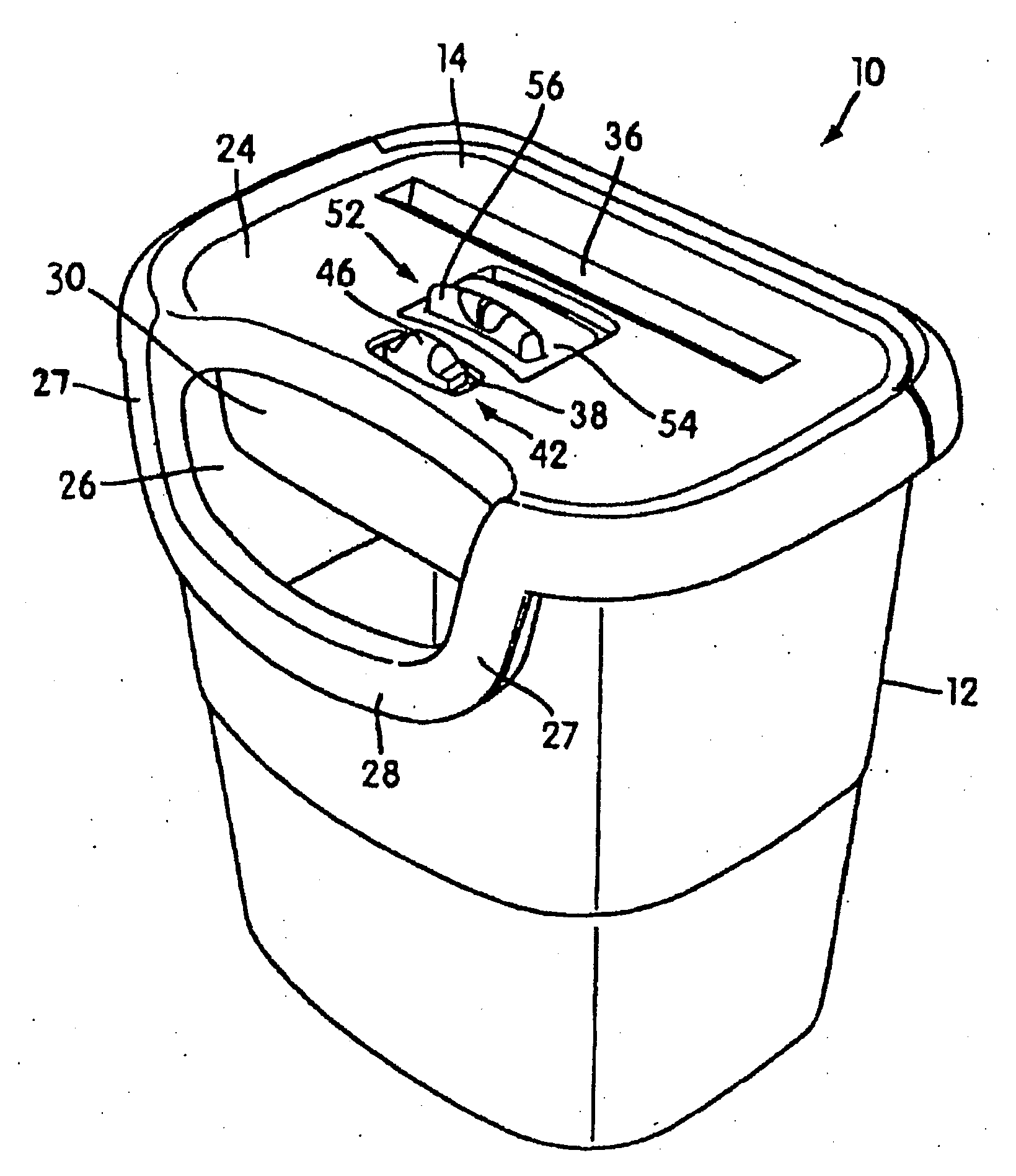
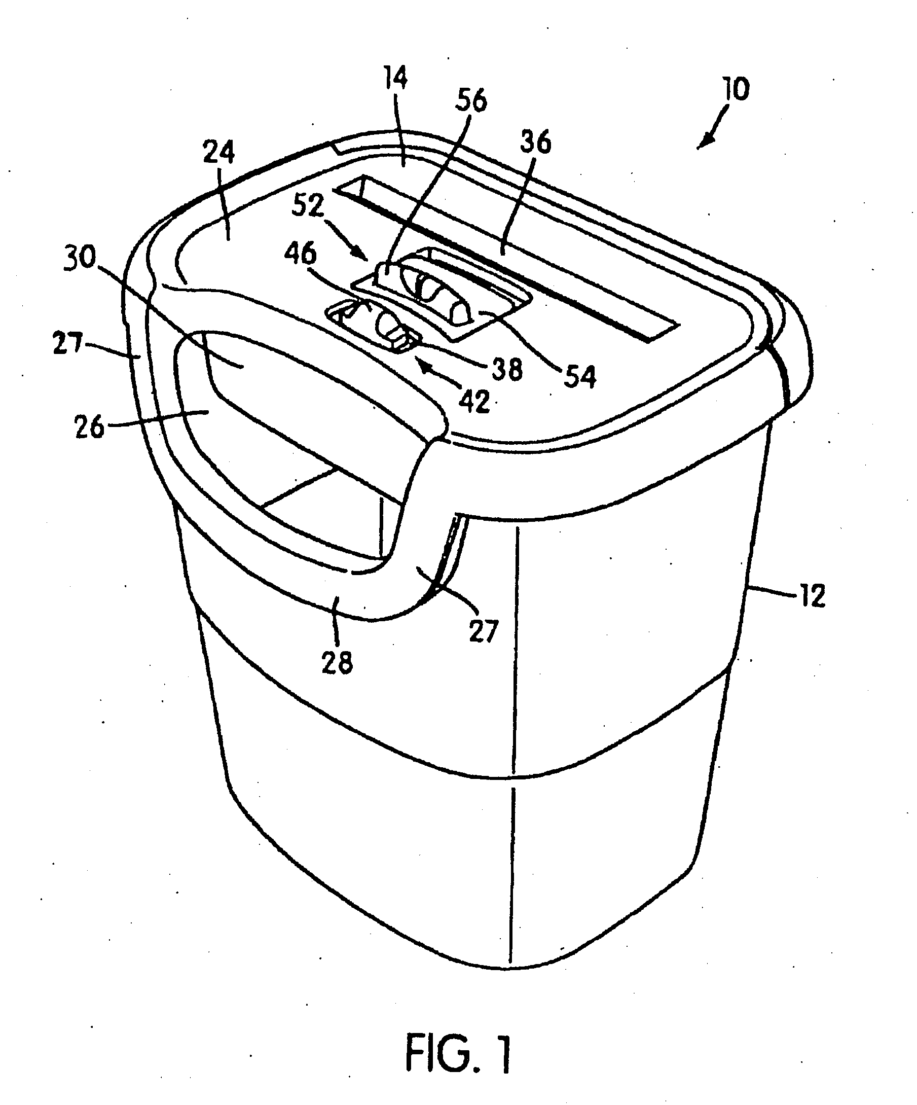
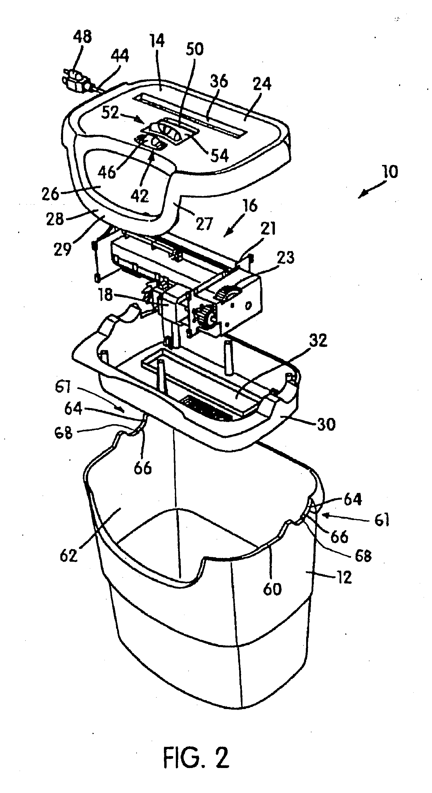
[0024]FIGS. 1 and 2 illustrate a shredder constructed in accordance with an embodiment of the present invention. The shredder is generally indicated at 10. In the illustrated embodiment, the shredder 10 sits atop a waste container, generally indicated at 12, which is formed of molded plastic or any other material. The shredder 10 illustrated is designed specifically for use with the container 12, as the shredder housing 14 sits on the upper periphery of the waste container 12 in a nested relation. However, the shredder 10 may also be designed so as to sit atop a wide variety of standard waste containers, and the shredder 10 would not be sold with the container. Likewise, the shredder 10 could be part of a large freestanding housing, and a waste container would be enclosed in the housing. An access door would provide for access to and removal of the container. Generally speaking, the shredder 10 may have any suitable construction or configuration and the illustrated embodiment is not...


PUM

PropertyMeasurementUnit
thicknessaaaaaaaaaa
thicknessaaaaaaaaaa
thicknessaaaaaaaaaa

Abstract

A shredder includes a housing having a throat for receiving at least one article to be shredded, and a shredder mechanism received in the housing and including an electrically powered motor and cutter elements. The shredder also includes a detector that is configured to detect a thickness of the at least one article being received by the throat, and a controller that is configured to operate the motor to drive the cutter elements to shred the at least one article and to set a flutter threshold higher than the predetermined maximum thickness threshold, if the detected thickness is less than a predetermined maximum thickness threshold. The controller is also configured to thereafter continuously detect the thickness of the at least one article being inserted into a throat of the shredder; and to perform a predetermined operation responsive to the thickness detector detecting that the thickness of the at least one article is greater than the flutter threshold.

Description

BACKGROUND OF THE INVENTION[0001]1. Field of the Invention[0002]The present invention relates to shredders for destroying articles, such as documents, compact discs, etc.[0003]2. Description of Related Art[0004]Shredders are well known devices for destroying articles, such as paper, documents, compact discs (“CDs”), expired credit cards, etc. Typically, users purchase shredders to destroy sensitive information bearing articles, such as credit card statements with account information, documents containing company trade secrets, etc.[0005]A common type of shredder has a shredder mechanism contained within a housing that is removably mounted atop a container. The shredder mechanism typically has a series of cutter elements that shred articles fed therein and discharge the shredded articles downwardly into the container. The shredder typically has a stated capacity, such as the number of sheets of paper (typically of 20 lb. weight) that may be shredded at one time; however, the feed thr...

Claims


Application Information

Patent Timeline
Patent Type & Authority Applications(United States)
IPC IPC(8): B02C25/00B02C18/00
CPCB02C18/0007B02C2018/164B02C2018/0038B02C25/00B02C18/16
Inventor MATLIN, TAI HOONJENSEN, MICHAEL DALE
Owner FELLOWES INC
Why Eureka
Try Eureka