Implant beam utilization in an ion implanter

a technology of implanter and beam, which is applied in the field of implanter, can solve the problems of low beam current at low energies, unsuitable high-dose or high-current ion implanters, and undesirable size of ion implanters

Active Publication Date: 2009-04-09
ADVANCED ION BEAM TECHNOLOGY INC
View PDF46 Cites 9 Cited by
  • Summary
  • Abstract
  • Description
  • Claims
  • Application Information

AI Technical Summary

Problems solved by technology

The scanning beam generation results in very low beam currents at low energies (200 to 5000 eV), which is unsuitable for high-dose or high-current ion implanters.
The multiple-wafer wheel makes an ion impl...

Method used


Image

  • Implant beam utilization in an ion implanter
  • Implant beam utilization in an ion implanter
  • Implant beam utilization in an ion implanter

Examples


Embodiment Construction

[0021]The following description sets forth numerous exemplary configurations, parameters, and the like. It should be recognized, however, that such description is not intended as a limitation on the scope of the present invention, but is instead provided as a description of exemplary embodiments.

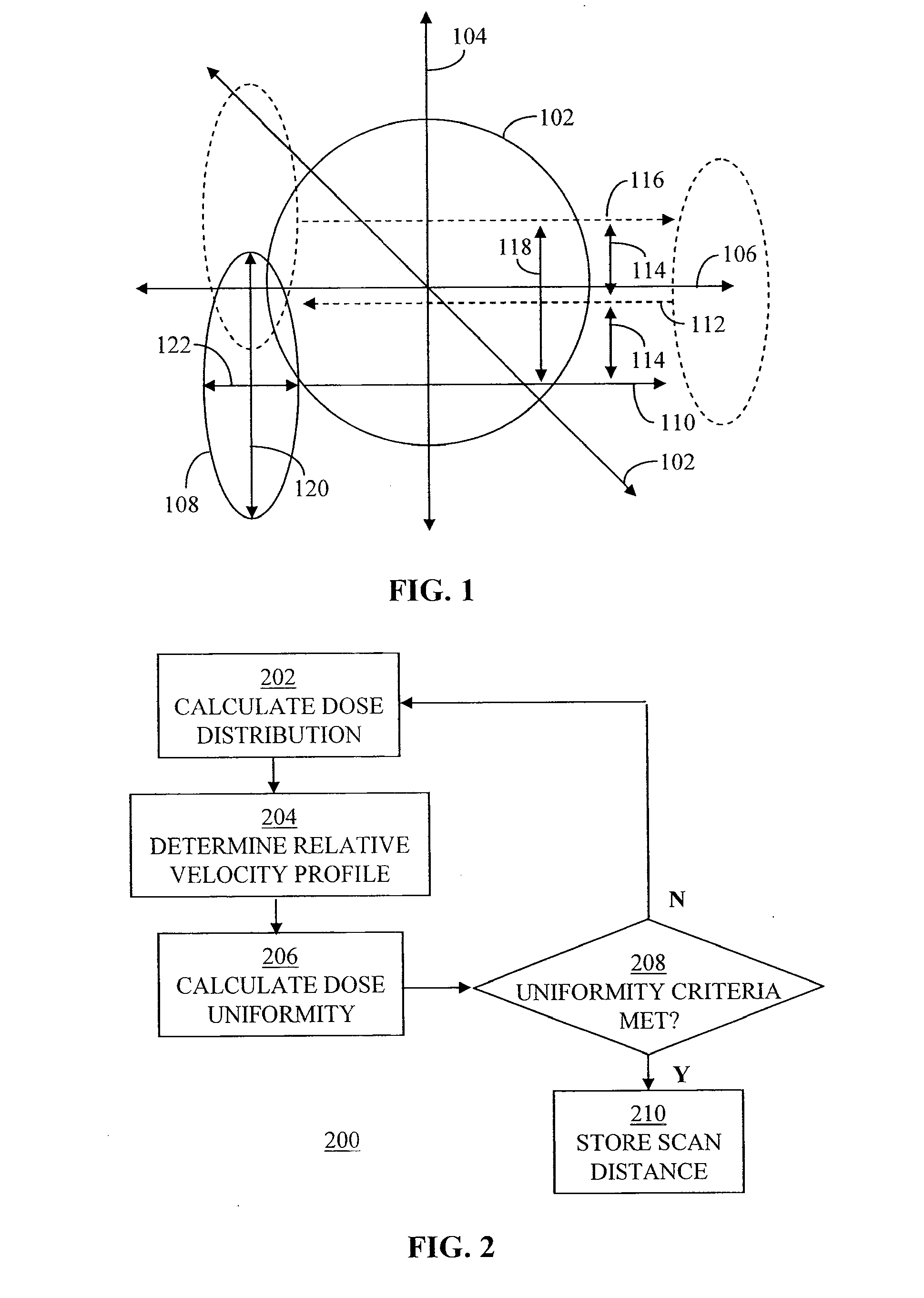
[0022]FIG. 1 depicts a wafer 102 to be implanted with dopant material. As depicted in FIG. 1, a first direction 104 and a second direction 106 along the surface of wafer 102 can be defined. First direction 104 and second direction 106 are about perpendicular to each other. It should be recognized, however, that first direction 104 and second direction 106 need not be precisely perpendicular. Also, while first direction 104 and second direction 106 are depicted as being vertical and horizontal, respectively, they can have various orientations.

[0023]To implant dopant material onto wafer 102, an implant beam 108 is scanned across wafer 102. In the present embodiment, implant beam 108 is scanned...


PUM


Abstract

To select a scan distance to be used in scanning a wafer with an implant beam, a dose distribution along a first direction is calculated based on size or intensity of the implant beam and a scan distance. The scan distance is the distance measured in the first direction between a first path and a final path of the implant beam scanning the wafer along a second direction in multiple paths. A relative velocity profile along the second direction is determined based on the dose distribution. Dose uniformity on the wafer is calculated based on the wafer being scanned using the relative velocity profile and the determined dose distribution. The scan distance is adjusted and the preceding steps are repeated until the calculated dose uniformity meets one or more uniformity criteria.

Description

BACKGROUND[0001]1. Field[0002]The present application relates generally to ion implanters; more specifically, this application relates to implant beam utilization in ion implanters for introducing dopant materials into silicon wafers.[0003]2. Related Art[0004]Typically, an ion implanter for introducing dopant materials into silicon wafers and other work pieces may be modeled into an ion beam generation system and an implant station where individual wafer(s) are mounted on the surface of an electrostatic chuck or a rotating disc that is scanned through the incoming ion beam. Because of larger and larger wafer sizes, the recent semiconductor processes have moved towards processing one wafer at a time, in so-called single-wafer systems.[0005]Traditional single-wafer ion implanters move the wafer in one direction past a fan shaped ion beam and an ion beam scan in a single axis. The scanning beam generation results in very low beam currents at low energies (200 to 5000 eV), which is unsu...

Claims


Application Information

Patent Timeline
IPC IPC(8): G21K5/10
CPCG21K5/10H01J37/304H01L21/68764H01J2237/20228H01J2237/31703H01J37/3171
Inventor SHEN, CHENG-HUIBERRIAN, DONALD WAYNECHEN, JIONG
Owner ADVANCED ION BEAM TECHNOLOGY INC
Why Eureka
Try Eureka