MRI apparatus

a magnetic resonance imaging and apparatus technology, applied in the field of magnetic resonance imaging apparatus, can solve the problems of inability to achieve high-quality image data, inability to obtain high-quality images, and inability to accurately detect the presence of fat components in the bone,

Active Publication Date: 2009-04-09
TOSHIBA MEDICAL SYST CORP
View PDF5 Cites 23 Cited by
  • Summary
  • Abstract
  • Description
  • Claims
  • Application Information

AI Technical Summary

Benefits of technology

[0013]According to one aspect of the present invention, a Magnetic Resonance Imaging (MRI) apparatus includes a flip-angle setting unit that sets a flip angle of a fat-suppression pulse, based on a scanning condition of an MRI scan and a fat-suppression level to which a fat-signal suppression method is applied; a transmitting-receiving unit that creates a fat-suppression pulse having the flip angle; a sequence control unit that controls irradiation of the fat-suppression pulse and application of a spoiler gradient magnetic field to a scan target portion of a subject, and suppresses an MR signal generated from fat tissue in the scan target portion to a predetermined magnitude; and an image-data creating unit that creates image data based on MR signals collected by applying a certain pulse sequence to the scan target portion in which the MR signal from the fat tissue is suppressed.
[0014]According to another aspect of the present invention, an MRI apparatus includes a fat-suppression level input unit that receives an input of a fat-suppression level of an MRI scan to which a fat-signal suppression method is applied; a scanning-condition setting unit that sets a parameter of a fat-suppression condition for fat suppression, based on a scanning condition of the MRI scan and the fat-suppression level; a sequence control unit that controls irradiation of a fat-suppression pulse with the set parameter and application of a spoiler gradient magnetic field to a scan target portion of a subject, and suppresses an MR signal generated from fat tissue in the scan target portion to a predetermined magnitude; and an image-data creating unit that creates image data based on MR signals collected by applying a certain pulse sequence to the scan target portion in which the MR signal from the fat tissue is suppressed.

Problems solved by technology

When creating image data from MR signals from water tissue, which are clinically effective, creation of image data of high quality may be difficult in some cases due to contamination by MR signals generated from fat tissue.
For example, when imaging bone and ligament tissue by performing an MRI scan onto a joint, MR signals collected from ligament tissue are originally feeble, and if a fat-signal suppression method is applied to the MRI scan, the MR signals collected from a bone that includes a number of fat components become extremely small.
As a result, it becomes difficult to display bone and ligament tissue with a clear distinction.
Thus, an MRI scan to which a conventional fat-signal suppression method is applied has a problem that tissue having a low density of hydrogen nuclear, or tissue from which small MR signals are collected in relation to a relaxation time and a pulse sequence, and tissue including a large number of fat components cannot be separately displayed.

Method used


Image

  • MRI apparatus
  • MRI apparatus
  • MRI apparatus

Examples


Embodiment Construction

[0030]Exemplary embodiments of the present invention will be explained below with reference to the accompanying drawings.

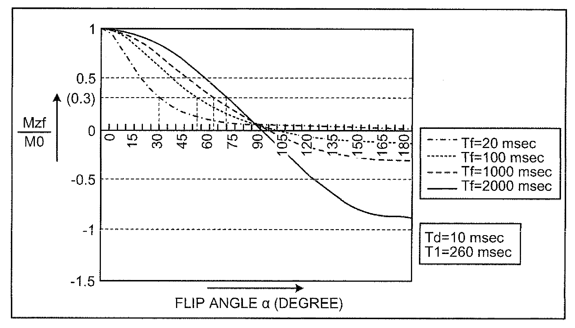
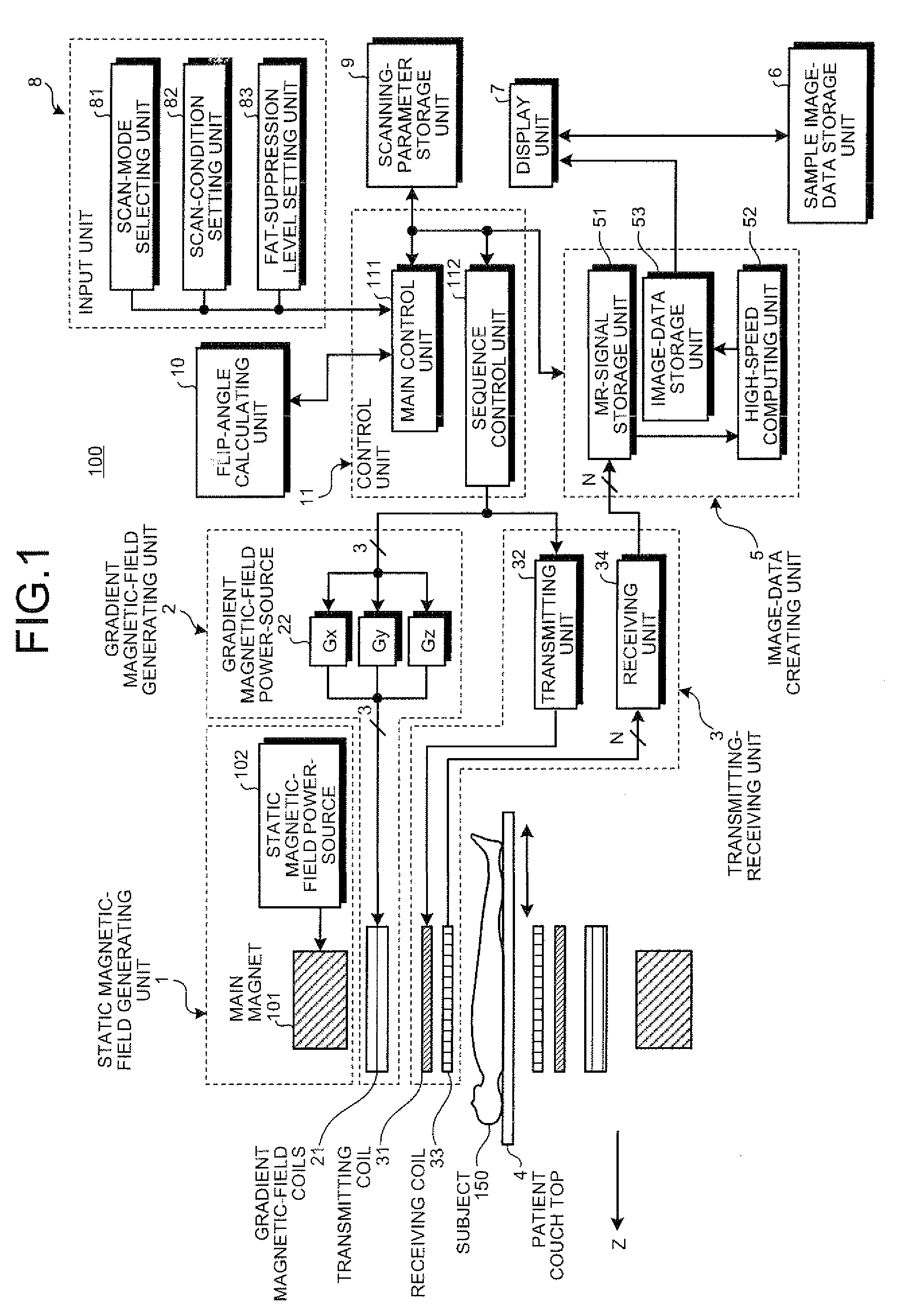
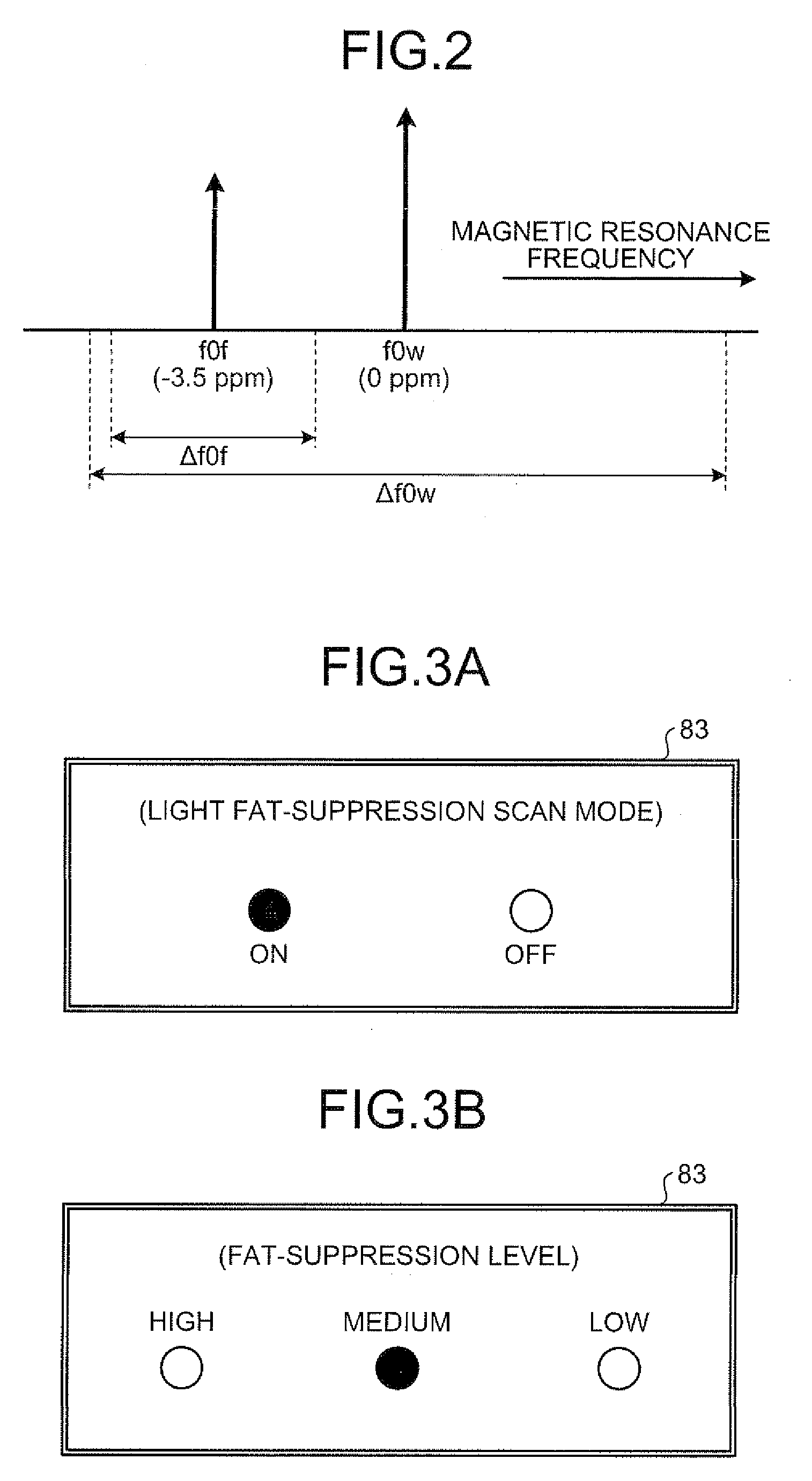
[0031]According to the following embodiments, first of all, a flip angle of a fat-suppression pulse is set based on scanning conditions of a Magnetic Resonance Imaging (MRI) scan to which a fat-signal suppression method is applied, and a fat-suppression level. Next, through a fat-suppression sequence aimed at suppressing a Magnetic Resonance (MR) signal generated from fat tissue (hereinafter, “fat signal”), a fat signal is suppressed to a desired level by performing irradiation of a fat-suppression pulse that has the flip angle and application of a spoiler gradient magnetic field onto a scan target portion of a subject. Then, through an MR-signal collection sequence following to the fat-suppression sequence, irradiation of a Radio Frequency (RF) pulse and application of a gradient magnetic field are performed onto the scan target portion in accordance with a certa...


PUM


Abstract

A flip-angle calculating unit calculates a flip angle of a fat-suppression pulse by inputting scanning parameters read from a scanning-parameter storage unit based on scanning conditions set by a scan-condition setting unit and a desired fat-suppression level, into a predetermined computing program. A control unit suppresses fat signals to a desired level by performing irradiation of a fat-suppression pulse having the calculated flip angle and application of a spoiler gradient magnetic field onto a scan target portion of a subject by controlling a gradient magnetic-field generating unit and a transmitting-receiving unit, and further performs irradiation of an RF pulse and application of a gradient magnetic field in accordance with a predetermined pulse sequence, thereby detecting water signals and suppressed fat signals as MR signals. An image-data creating unit creates image data by reconstructing the MR signals.

Description

CROSS-REFERENCE TO RELATED APPLICATIONS[0001]This application is based upon and claims the benefit of priority from the prior Japanese Patent Application No. 2007-261360, filed on Oct. 4, 2007, and Japanese Patent Application No. 2008-212455, filed on Aug. 21, 2008; the entire contents of which are incorporated herein by reference.BACKGROUND OF THE INVENTION[0002]1. Field of the Invention[0003]The present invention relates to a Magnetic Resonance Imaging (MRI) apparatus, and particularly relates to an MRI apparatus that suppresses a Magnetic Resonance (MR) signal generated from fat tissue by applying a fat-signal suppression method.[0004]2. Description of the Related Art[0005]A Magnetic Resonance Imaging (MRI) method is an imaging method of creating image data based on Magnetic Resonance (MR) signals generated along with excitation produced by exciting a nuclear spin in a substance placed in a static magnetic field with a high frequency pulse (Radio Frequency (RF) pulse) that has a ...

Claims


Application Information

Patent Timeline
Patent Type & Authority Applications(United States)
IPC IPC(8): G01R33/54
CPCG01R33/4828G01R33/5602G01R33/5617G01R33/5616G01R33/5607
Inventor SUGIURA, SATOSHI
Owner TOSHIBA MEDICAL SYST CORP
Why Eureka
Try Eureka