Low voltage synchronous oscillator for dc-dc converter

a synchronous oscillator and converter technology, applied in the field of oscillator circuits, can solve the problems of low output voltage of the battery, unsatisfactory oscillator availability, and all such batteries tend to suffer voltage sag (decreased voltage output), and achieve the effect of facilitating their use and low cos

Active Publication Date: 2009-04-09
HONG KONG APPLIED SCI & TECH RES INST
View PDF8 Cites 12 Cited by
  • Summary
  • Abstract
  • Description
  • Claims
  • Application Information

AI Technical Summary

Benefits of technology

[0009]Oscillator circuit configurations of the present invention do not require programmed delays or complex delay tuning circuits, and thus avoid the disadvantages associated with such circuits. Accordingly, oscillator circuits of the present invention operate reliably at very low voltages, such as 0.6 Volts in a CMOS implementation, thereby facilitating their use even in the startup of boost and buck-boost DC-DC converter circuits. Moreover, oscillator circuits of the present invention may be implemented using little physical space (e.g., die area) and at little cost.

Problems solved by technology

For example, some commercially available batteries may provide an output voltage which is too high whereas some commercially available batteries may provide an output voltage which is too low, while no commercially available battery provides an output voltage which is exactly that required by a circuit of a particular electronic device.
Similarly, due to such considerations as size (e.g., for enhanced portability), a small form-factor battery may be utilized with respect to an electronic device, although that particular battery does not provide an output voltage required by circuits of the electronic device.
Further aggravating this mismatch of battery output voltage to electronic device circuit voltage requirements is the fact that all such batteries tend to suffer voltage sag (decreased voltage output) with time and / or use.
Accordingly, even where the output voltage of a battery initially meets circuit voltage requirements, the output voltage of the battery will not likely continue to meet the circuit voltage as the electronic device sees use.
The oscillators that have heretofore been available for use in DC-DC converters have not been ideal.
However, it has been found that such delays, although fixed in the sense that they are not controllably adjustable, are not in fact fixed in the operating environment.
As the delays provided in the oscillator circuit change, the trigger signal output becomes asynchronous, resulting in overlapping trigger signal output and failure of the DC-DC converter.
These oscillators are typically very complicated, employing both analog and digital circuits, consume appreciable physical space, and are not easily implemented.
Moreover, if the programmable delay is in error (e.g., the models used in predicting the needed delay are inaccurate, there are differences introduced to the circuit through integrated circuit process variations, etc.) the trigger signal output may be asynchronous, resulting in overlapping trigger signal output and failure of the DC-DC converter.
Although such tuning circuits may be somewhat effective in controlling delay in response to variations in operating conditions, such as changes in operating voltage, the use of such circuits is not without disadvantage.
For example, the delay tuning circuits are typically complicated and add cost, complexity, and physical size to the DC-DC converters.
The complexity of delay tuning circuits can result in integrated circuit process variations producing inoperable or unpredictable circuits.
Moreover, delay tuning circuits often implement voltage sensors which are ineffective at low voltages (e.g., 0.8 Volts) and thus cannot be used to provide reliable and accurate voltage conversion through much of many battery's life cycle.
Such limits on low voltage operation is particularly problematic in the startup of boost or buck-boost DC-DC converter circuits where higher voltages provided by the converter are not available.
Additionally, although operating to control delays to maintain non-overlapping trigger signal output, such delay tuning circuits often do not maintain a constant duty cycle with respect to the trigger signal output, and thus the DC-DC converter voltage output is not constant.

Method used


Image

  • Low voltage synchronous oscillator for dc-dc converter
  • Low voltage synchronous oscillator for dc-dc converter
  • Low voltage synchronous oscillator for dc-dc converter

Examples


Embodiment Construction

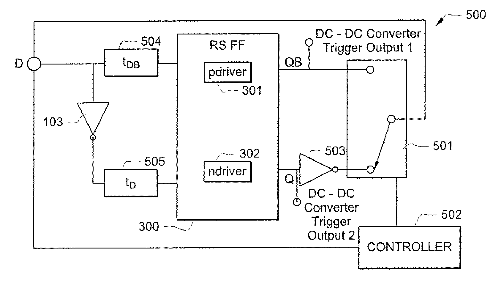
[0025]In arriving at the present invention, it was realized that in order to provide reliable and accurate voltage conversion, oscillators used in DC-DC voltage converters should meet several operational criteria. Specifically, such oscillators should provide stable self oscillation, the oscillation providing synchronized or non-overlapping trigger signal output, and the duty cycle of the oscillation should be constant. The various oscillator circuits which have previously been proposed for use in DC-DC converters were found to provide unsatisfactory performance with respect to one or more of the foregoing operational criteria. Moreover, many of the previous oscillator circuits are complex, costly, and / or require appreciable physical space (e.g., requiring an undesirable amount of integrated circuit die space).

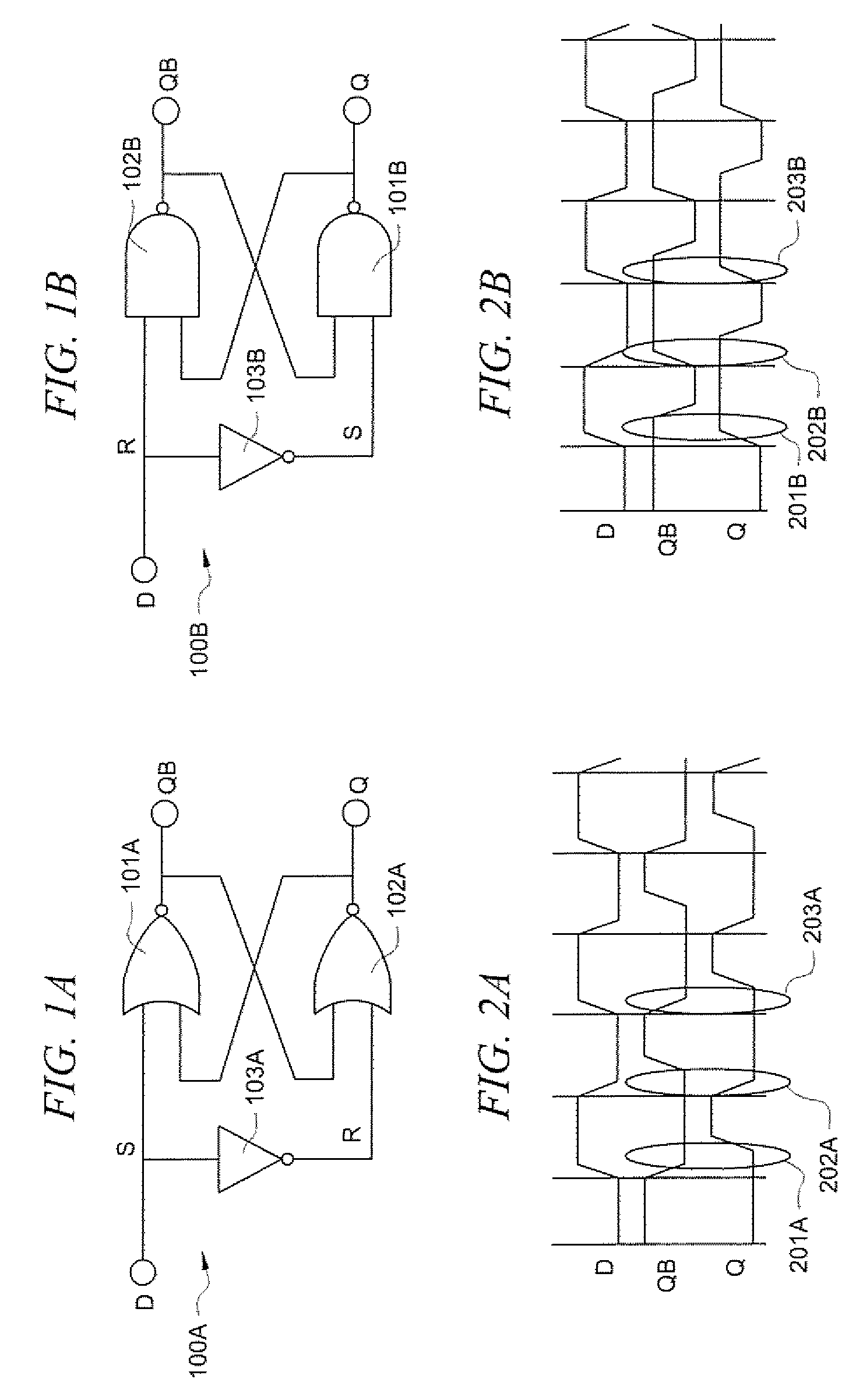
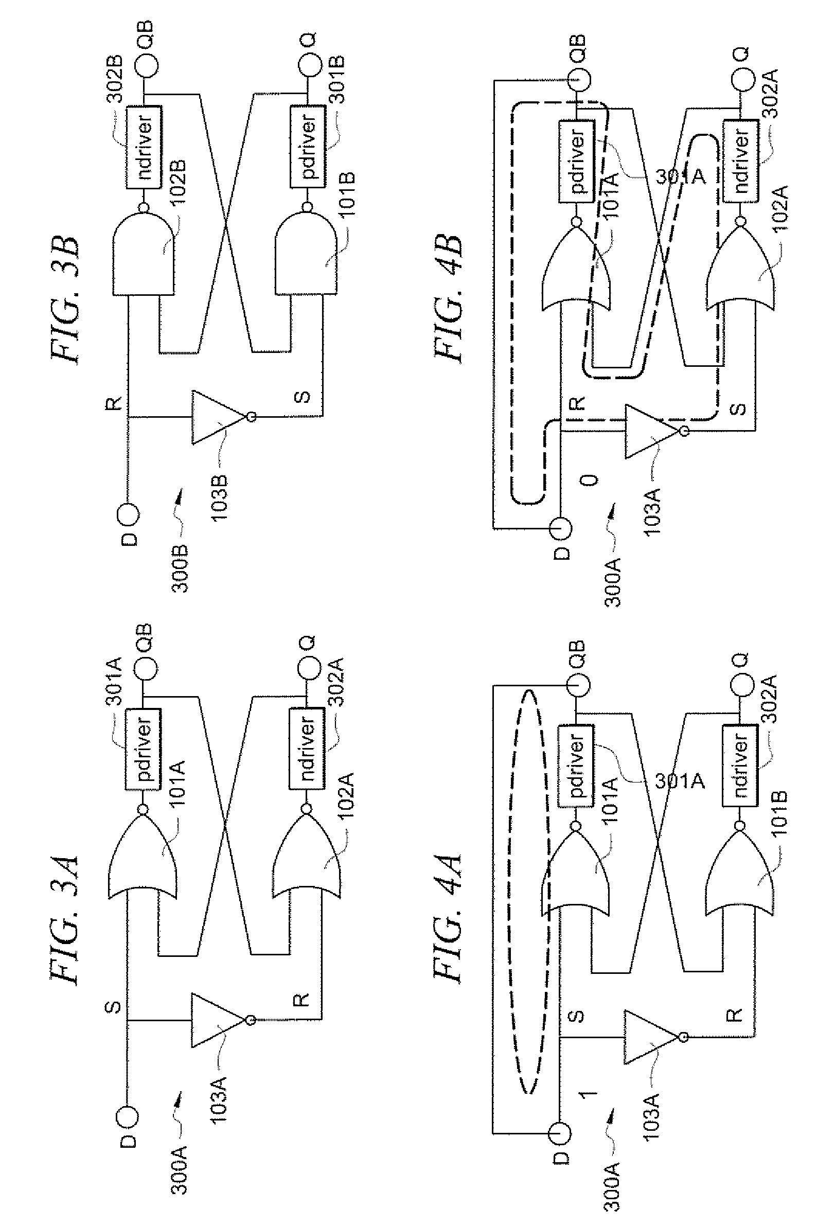
[0026]Directing attention to FIGS. 1A, 1B, 2A, and 2B, it can be seen that RS flip-flop circuit configurations may be utilized to provide non-overlapping trigger signal output...


PUM


Abstract

Systems and methods which provide an oscillator circuit outputting non-overlapping trigger signals throughout a range of operating voltages using a reset-set (RS) flip-flop type circuit configuration are shown. Embodiments utilize output driver buffers internal to the RS flip-flop circuit configuration to provide oscillator feedback delay. Feedback control circuitry may be implemented to ensure that the delay associated with any one driver buffer does not solely provide the feedback delay. Embodiments further implement input delay circuitry adapted to maintain a relatively constant reset and set input feedback delay ratio throughout a large range of operating conditions.

Description

TECHNICAL FIELD[0001]The present invention relates generally to oscillator circuits and, more particularly, to oscillator circuits useful in DC-DC converter applications.BACKGROUND OF THE INVENTION[0002]Electronic devices used for personal and business purposes have become ubiquitous. For example, many persons use personal computers, calculators, entertainment systems, and telephones in their personal and professional lives everyday. Many such electronic devices are portable, and thus include an independent power supply, such as in the form of a battery or batteries.[0003]Batteries used as the foregoing power supplies provide a direct current (DC) source. Commercially available batteries are generally provided in various configurations having predetermined capacities and output voltages. Often times, a battery must be used which provides a DC output voltage different than that required by one or more circuits of an electronic device the battery is to power. For example, some commerc...

Claims


Application Information

Patent Timeline
Patent Type & Authority Applications(United States)
IPC IPC(8): H03K3/03
CPCH03K3/017H03K5/133H03K5/1515
Inventor WONG, YAT TONG, DAVID CHIK WAIWAN, KAM CHUENKWONG, DAVID KWOK KUEN
Owner HONG KONG APPLIED SCI & TECH RES INST
Why Eureka
Try Eureka