[0009]An object of the present invention is to set down an industrial automation device in which the display functionality is improved.
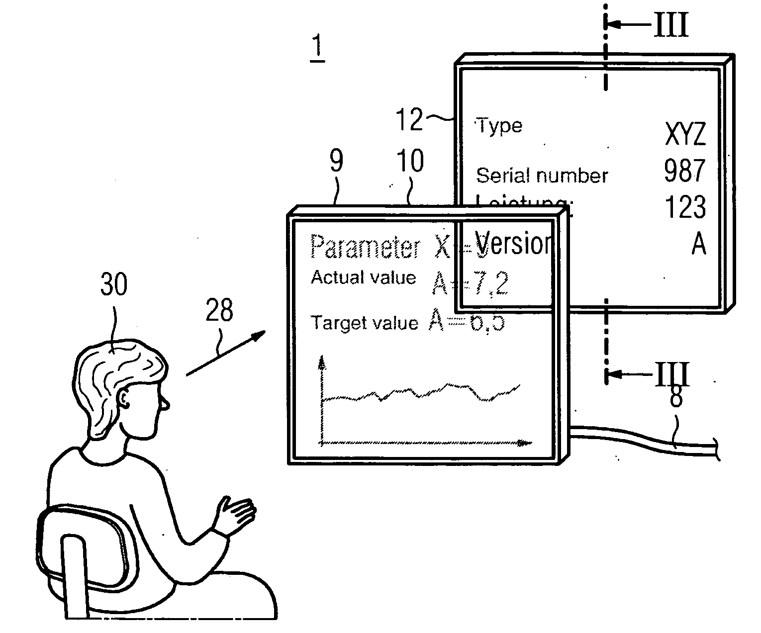
[0012]A display system according to the invention has a first display panel, whereby the first display panel can be operated electrically and is at least partially and / or at times transparent. This first display panel corresponds for example to the display panel of a transparent LCD display or a transparent
OLED display (TOLED). Furthermore, the display system according to the invention has a second display panel, whereby the first display panel is positioned in such a manner with respect to the second display panel that the second display panel can be viewed through the first display panel. The first display panel and the second display panel are therefore positioned behind one another, whereby this positioning in particular affects the lines of
sight in which both the first display panel and also the second display panel can be viewed simultaneously. The transparency of the first display panel in particular exists only partially as a rule during the display because the display is effected by a difference in contrast and depending on a positive display or on a negative display there are areas of the display panel which either exhibit a good transparency or also exhibit a reduced transparency. A reduced transparency can ultimately result in intransparency.
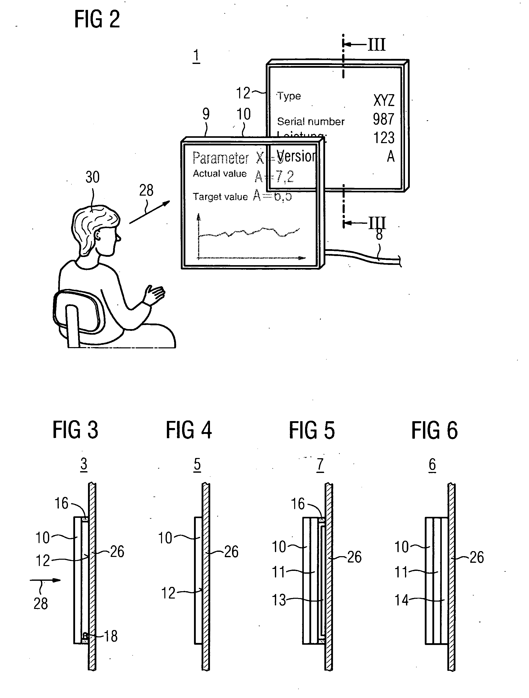
[0032]According to a further embodiment of the display system, this has a third display panel, whereby the third display panel is positioned between the first display panel and the second display panel. The third display panel for example can be operated electrically, whereby like the first display panel it can additionally exhibit an operating state which makes it possible to influence the transparency at least partially and / or at times. It is advantageous if the third display panel can be made nontransparent at least partially and / or at times or only to a limited extent. If the third display panel or also a further display panel between the first and the second display panel is intransparent or if this forms a dark background for the first display panel, this first display panel can be better read. If the second display panel is intended to be easily read by a person, then the third display panel or a further display panel is made transparent between the first and the second.
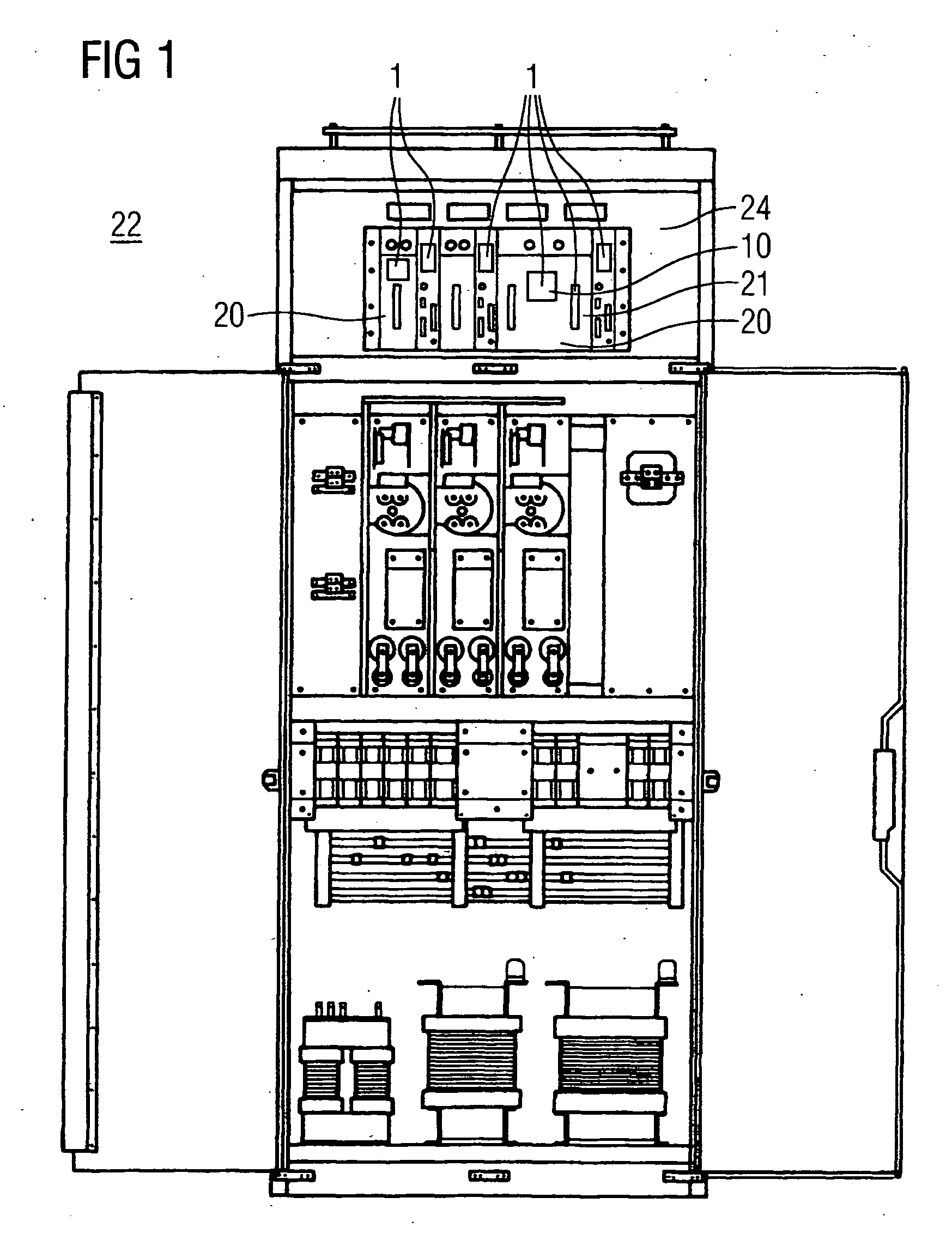
[0034]The display system according to the invention is advantageously mounted on an industrial automation device. This also includes the fact that the display system is integrated into the industrial automation device. The trend towards an ever smaller construction method can be observed particularly in the case of industrial automation devices. As a result, the surface area which can be used for representing and displaying information is reduced in size. By using the display system according to the invention for the industrial automation device (this is for example a PLC controller, a power converter, a CNC controller, a
power supply unit, a regulation facility, . . . ) it is then possible to utilize a surface area of the industrial automation device in twofold fashion for displaying information. The display can thus advantageously for example be made larger such that it can be read more easily and / or from a greater distance. If an
identification plate for the industrial automation device is now used as a second display panel, the
identification plate can also be easily read. In order to improve the
readability, the first display panel must be switched to transparent.
[0036]In addition, the invention relates to a method for operating a display system, whereby the display system in particular has an embodiment of the forms described above. The display system has a first display panel, whereby this can be operated electrically and is at least partially and / or at times transparent and it has a second display panel, whereby the first display panel is positioned in such a manner with respect to the second display panel that the second display panel can be viewed through the first display panel by a person, whereby the first display panel is operated in an at least partially transparent state. If the display system has a third display panel, whereby the third display panel is positioned between the first display panel and the second display panel, whereby the third display panel can be operated electrically and is at least partially and / or at times nontransparent, the third display panel is for example controlled electrically in such a manner that it becomes more opaque and maintains this state. The second display panel is hidden as a result. This enables better viewing of the first display panel or of the display panel which is situated in front of the third display panel in the viewing direction. The method can also be used in the case of a display system for an industrial automation device. In this case, it has the
advantage for example that when the industrial automation device is switched off the display system is also switched off or can be switched off and in this state, for example during installation of the industrial automation device, the
identification plate can be easily read as a second display panel behind for example an
OLED display panel and the industrial automation device can thus be easily identified. When the industrial automation device is operating, in order to read the identification plate it is then for example possible to deactivate, or make transparent, the first display panel, which can be controlled electrically.

