Light scanning apparatus, light scanning method, image forming apparatus, color image forming apparatus, and recording medium having program

a light scanning and image forming technology, applied in the direction of electrical devices, instruments, printing, etc., can solve the problems of fluctuation of the amount of light emitted from the light source, the difficulty of setting the light intensity of a semiconductor laser at a specific value, and the difficulty of printing speed and image quality improvement with such conventional methods

Inactive Publication Date: 2009-04-09
RICOH KK
View PDF4 Cites 43 Cited by
  • Summary
  • Abstract
  • Description
  • Claims
  • Application Information

AI Technical Summary

Benefits of technology

[0019]As described above, embodiments of the present invention make it possible to control plural light sources to form L (L≧2) light beam arrays aligned in a sub scanning direction each of which L light beam arrays are formed by causing M ((N−1)≧M≧1) light sources (M light emitting sources) out of N (N≧2) light sources assigned to each of the L light beam arrays to emit light, wherein each of the L light beam arrays forms a pixel and a total of L pixels aligned in the sub scanning direction are formed.

Problems solved by technology

However, further improvements in printing speed and image quality would be difficult with such conventional methods.
However, since the light output of a semiconductor laser at a driving current fluctuates depending on the temperature, it is difficult to set the light intensity of a semiconductor laser at a specific value.
Especially, in a surface emitting laser array having plural light sources on a single chip, since the distances between the light sources are short, temperature changes caused by light emission and extinction and temperature cross-talk cause the amount of light emitted from the light sources to fluctuate.
However, in a conventional light scanning apparatus having plural light sources, since one pixel is normally formed with one light source, it is difficult to correct the position of a pixel with an accuracy higher than the size of the pixel.

Method used


Image

  • Light scanning apparatus, light scanning method, image forming apparatus, color image forming apparatus, and recording medium having program
  • Light scanning apparatus, light scanning method, image forming apparatus, color image forming apparatus, and recording medium having program
  • Light scanning apparatus, light scanning method, image forming apparatus, color image forming apparatus, and recording medium having program

Examples


Embodiment Construction

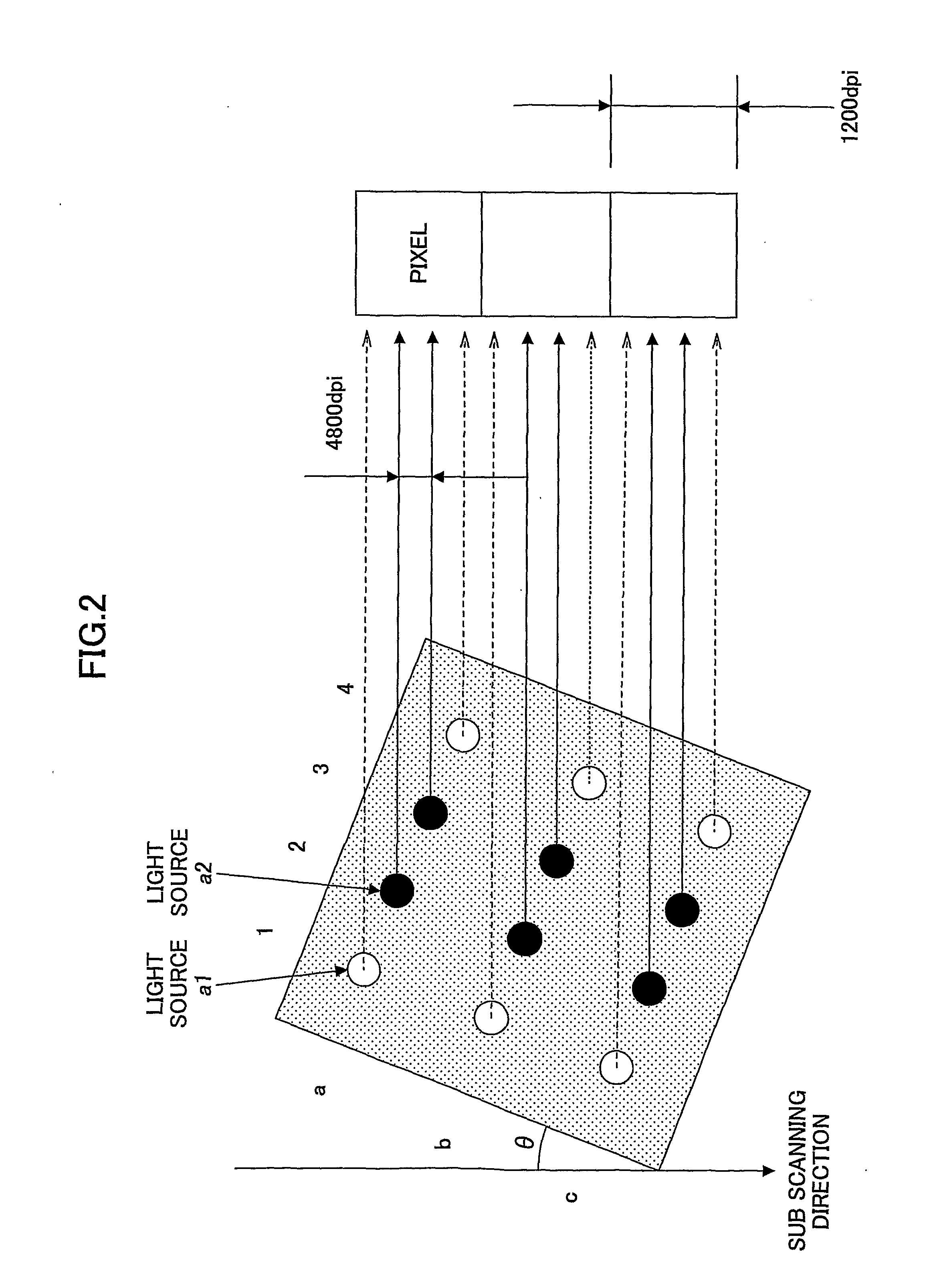
[0052]Preferred embodiments of the present invention are described below with reference to the accompanying drawings. In the present invention, a pixel means a simple pixel (for example, a pixel in a 1,200 dpi image has a size of 21 μm square) and does not refer to a compound pixel made up of plural pixels (for example, 4×4 pixels) as in a dithering technique.

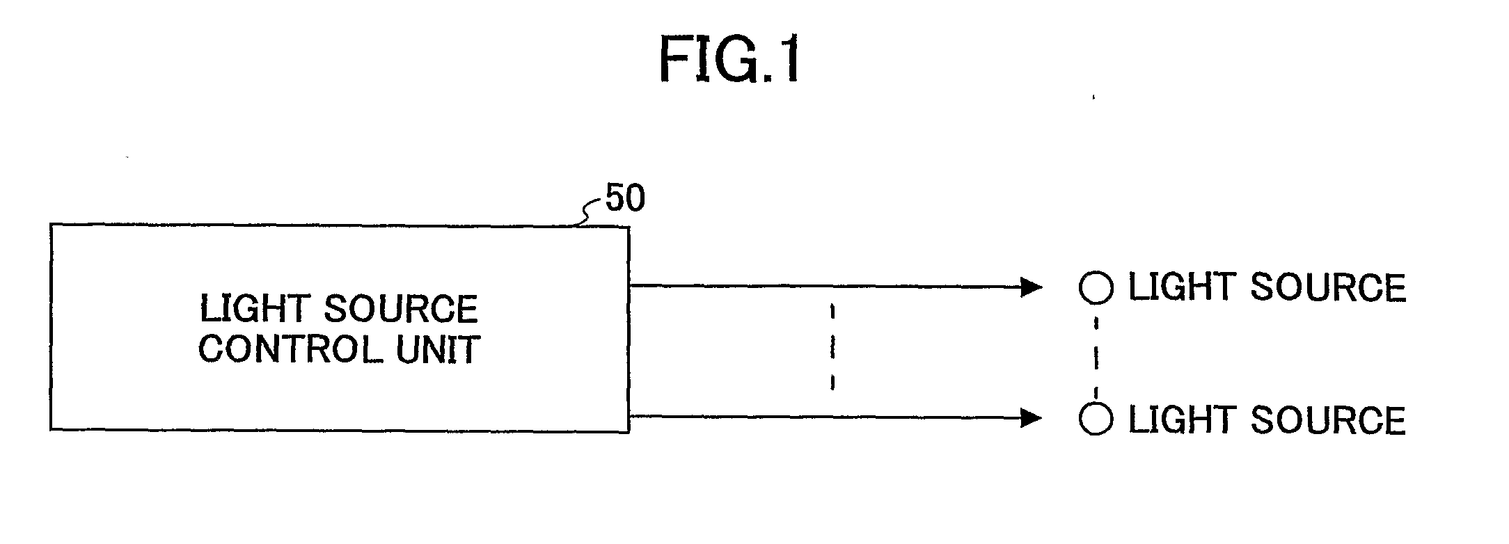
[0053]FIG. 1 is a drawing illustrating an exemplary configuration of a light scanning apparatus according to an embodiment of the present invention. As shown in FIG. 1, a light scanning apparatus according to an embodiment of the present invention (a light scanning apparatus that scans plural light beams from plural light sources in the main scanning direction) includes a light source control unit 50 that controls plural light sources. When plural light sources (for example, a two-dimensional array of plural light sources) are used, the arrangement of light emitting points of the light sources and the arrangement of light beams...


PUM


Abstract

A light scanning apparatus having plural light sources includes a light source control unit configured to control the light sources to form L (L≧2) light beam arrays aligned in a sub scanning direction each of which L light beam arrays are formed by causing M ((N−1)≧M≧1) light sources out of N (N≧2) light sources assigned to each of the L light beam arrays to emit light as M light emitting sources, wherein each of the L light beam arrays forms a pixel and a total of L pixels aligned in the sub scanning direction are formed.

Description

TECHNICAL FIELD[0001]The present invention generally relates to a light scanning apparatus, a light scanning method, an image forming apparatus, a color image forming apparatus, and a recording medium having a program, and more particularly relates to a light scanning apparatus, a light scanning method, an image forming apparatus, a color image forming apparatus, and a recording medium having a program that use plural light sources and can precisely correct the position of a pixel in the sub-scanning direction.BACKGROUND ART[0002]FIG. 32 is a block diagram illustrating an exemplary configuration of an electrophotographic image forming apparatus such as a laser printer or a digital copier. As shown in FIG. 32, a laser beam emitted from a semiconductor laser unit 1001 used as a light source unit is deflected and scanned by a rotating polygon mirror 1002, passes through a scanning lens (fθ lens) 1003, and forms a light spot on a photoconductor 1004, thereby exposing the photoconductor ...

Claims


Application Information

Patent Timeline
Patent Type & Authority Applications(United States)
IPC IPC(8): H04N1/04
CPCB41J2/473G02B26/123B41J2/455H04N1/40031H04N1/1135
Inventor TANABE, JUNISHIDA, MASAAKINIHEI, YASUHIROOMORI, ATSUFUMI
Owner RICOH KK
Why Eureka
Try Eureka