Fastening element

a technology of fastening element and ring, which is applied in the direction of screws, dowels, artificial islands, etc., can solve the problems of insufficient slight intermixing of components and only slightly intermixing of hardenable mass that exits through the through-opening, and achieve the effect of limiting the displacement of mixing elements

Inactive Publication Date: 2009-04-09
HILTI AG
View PDF37 Cites 7 Cited by
  • Summary
  • Abstract
  • Description
  • Claims
  • Application Information

AI Technical Summary

Benefits of technology

[0012]With the drilling head of the inventive fastening element, different setting processes, using the inventive fastening element, can be implemented. The inventive fastening element is easy to produce as no mechanical measures must be implemented in the fastening element in order to insure a satisfactory intermixing of the hardenable mass.
[0015]The fastening element can be simply and cost-effectively produced and can be used in different setting processes. The simple design of the fastening element permits to prevent assemblage error. For different constructional components or rock materials, different drilling heads can be provided on the anchor tube. This adaptation of the fastening element can be easily effected by the user because the danger of malfunction of the fastening element after replacement of the drilling head can be substantially excluded.
[0017]Advantageously, the mixing element is clampingly retained in the drilling head. The mixing element can have, e.g., at least in some regions, an excessive size relative to the receptacle for the mixing element provided in the drilling head. Therefore, during mounting of the mixing element, it is held in the drilling head without a possibility of being lost. Alternatively, the mixing element is glued in the receptacle, which is provided in the drilling head, at least in some regions. The fixation of the mixing element in the drilling head advantageously is so effected that, simultaneously, a circumferential sealing of the mixing element in the drilling head receptacle is provided.
[0018]Advantageously, a stop for the mixing element is provided between the mixing element and the at least one through-opening. The stop prevents mixing element, when the mixing element is displaced by the hardenable mass to which pressure is applied, from being displaced so far in the drilling head that it would close the at least one through-opening, so that a sufficient amount of the hardenable mass would not be able to exit the anchor tube for a satisfactory anchoring of the anchor tube in the constructional component.
[0019]Advantageously, the stop is formed as a plate-shaped member having at least one through-opening for the hardenable mass. The plate-shaped form of the stop provide an adequate stop surface for the mixing element for reliably limiting the displacement of the mixing element in the direction of the at least one through-opening. In addition, the mixing element, in particular when formed of a plastic material, could not be so deformed that it would slide over the stop in the drilling head upon application of high pressure to the hardenable mass.
[0020]Advantageously, the drilling head has a circumferential bead sealingly engageable with the second end of the anchor tube. Because the fastening element, during the ejection process, is supported against the borehole bottom by the drilling head, a satisfactory sealing of the contact surface between the drilling head and the end of the anchor tube is insured. The produced sealing prevents a sidewise exit of the hardenable mass, without affecting the flow of the hardenable mass through the mixing element. According to an advantageous embodiment of the invention, an additional sealing element, e.g., in form of a sealing ring, is provided on the head.

Problems solved by technology

The drawback of the fastening element of the U.S. Pat. No. 4,055,051 consists in that the hardenable mass that exits through the through-opening is intermixed only slightly.
For an optimal anchoring of the fastening element, with multi-component masses, the slight intermixing of the components is often not sufficient.

Method used


Image

  • Fastening element
  • Fastening element

Examples


Embodiment Construction

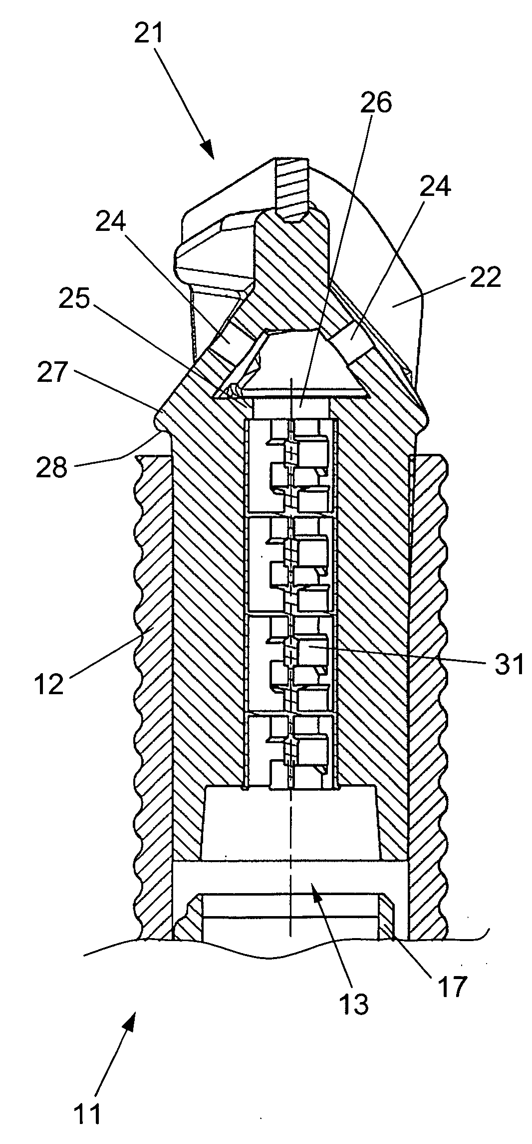
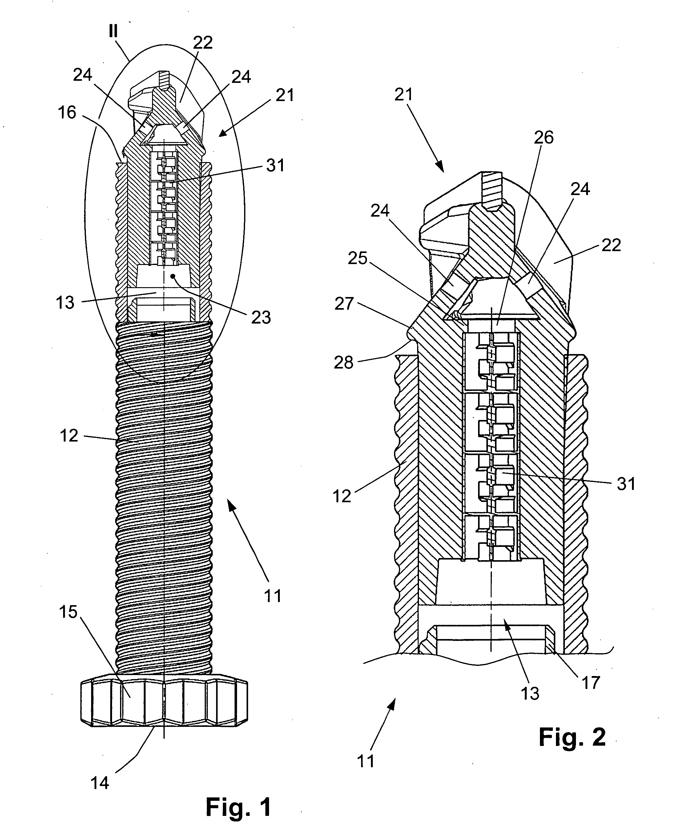
[0025]A fastening element 11 according to the present invention, which is shown in FIGS. 1-2, includes an anchor tube 12 having a receiving chamber 13 for a hardenable mass. At first end 14 of the anchor tube 12, there is provided rotation transmitting means 15 in form of a polygon for a power drill, not shown. At a second end 16 of the anchor tube 12 opposite the first end 14, there is provided a drilling head 21. In the receiving chamber 13 of the anchor tube 12, there is arranged an inner tube 17 that serves as a receptacle for the hardenable mass.

[0026]The drilling head 21 has a drilling bit 22, an inlet opening 23 that opens toward the receiving chamber 13, and two through-openings 24 that open outwardly for passing the hardenable mass therethrough. In the drilling head 21, between the inlet opening 23 and the through-openings 24, there is provided a static mixer for the hardenable mass in form of a mixing element 31. The mixing element 31 is clampingly retained in the drilling...


PUM


Abstract

A fastening element has a drilling head (21) provided at one end (16) of anchor tube (12) and having at least one inlet opening (23) that opens toward the receiving chamber (13) of the anchor tube (12), and at least one through-opening (24) that opens outwardly for passing of the hardenable mass therethrough, and a mixing element (31) for the hardenable mass and which is located in the drilling head (21) between the at least one inlet opening (23) and the at least one through-opening (24).

Description

BACKGROUND OF THE INVENTION[0001]1. Field of the Invention[0002]The present invention relates to a fastening element including an anchor tube having a receiving chamber for a hardenable mass, and drilling head provided at one end of the anchor tube and having at least one inlet opening that opens toward the receiving chamber of the anchor tube, and at least one through-opening that opens outwardly for passing of the hardenable mass therethrough.[0003]2. Description of the Prior Art[0004]Fastening elements of the type described above are used, e.g., for reinforcement of tunnels and mines. To this end, firstly, a borehole is formed in a tunnel or mine roof, e.g., then the borehole is filled with a hardenable mass and, finally, an anchor element is driven into the borehole filled with the hardenable mass.[0005]International Publication WO 03 / 044324 discloses a fastening element including an anchor tube that forms the anchor element and has a receiving chamber for a hardenable mass and ...

Claims


Application Information

Patent Timeline
Patent Type & Authority Applications(United States)
IPC IPC(8): E21D9/00
CPCE21D20/02E21D2021/0053F16B35/044F16B13/141F16B13/003E21D21/0053
Inventor BAYERL, MICHAELLUDWIG, WOLFGANGHEEMANN, KAY
Owner HILTI AG
Why Eureka
Try Eureka