
Portable terminal device

a terminal device and portability technology, applied in power management, near-field systems using receivers, high-level techniques, etc., can solve the problems of user inability to go out of the station or the premise, non-contact ic function cannot be used, non-contact ic cannot be used, etc., to achieve the extension of available time and estimated available time

Inactive Publication Date: 2009-04-09
PANASONIC CORP
View PDF0 Cites 8 Cited by
  • Summary
  • Abstract
  • Description
  • Claims
  • Application Information

AI Technical Summary

Benefits of technology

[0017](3) A portable terminal device that can display an operable state of a noncontact IC and makes a user feel secure
[0019]This configuration can extend the available time of the noncontact IC after stopping the power supply to the portable phone function.
[0021]Thanks to this configuration, the noncontact IC can be operated even when the battery residual quantity becomes small, by supplying the power generated by direct-current conversion to the noncontact IC.
[0023]Thanks to this configuration, the power generated by the direct-current conversion can be supplied to the noncontact IC, and the noncontact IC can be operated even when the battery residual quantity of the noncontact IC dedicated battery becomes small.
[0024]The portable terminal devices allow extension of the available time of the noncontact IC and allow visual recognition of the estimated available time.

Problems solved by technology

(1) Operable Voltage
Therefore, even at a battery voltage at which the portable phone function cannot be used but the noncontact IC function can be used, the noncontact IC function cannot be used.
Therefore, in a usage pattern where the noncontact IC is used twice or more, the power supply can turn off due to reduction in voltage and the noncontact IC cannot be necessarily used twice or later.
In a usage pattern where a user uses the noncontact IC in coming into or coming out of a station or a premise, for example, if the power supply turns off after coming into the station or the premise, the noncontact IC cannot be used and the user cannot go out of the station or the premise, disadvantageously.
Therefore, a user can feel insecure.

Method used


Image

  • Portable terminal device
  • Portable terminal device
  • Portable terminal device

Examples


first exemplary embodiment

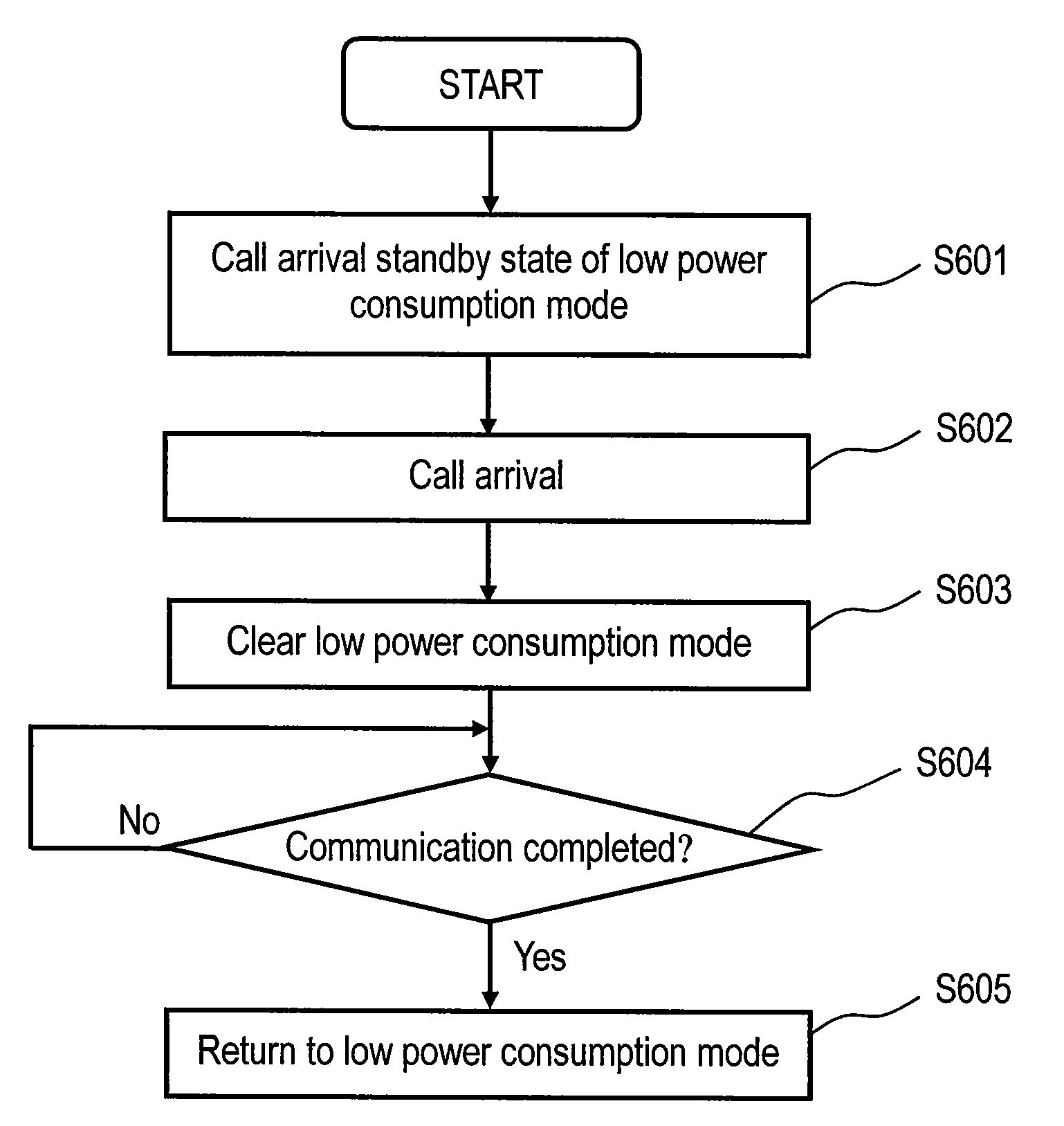
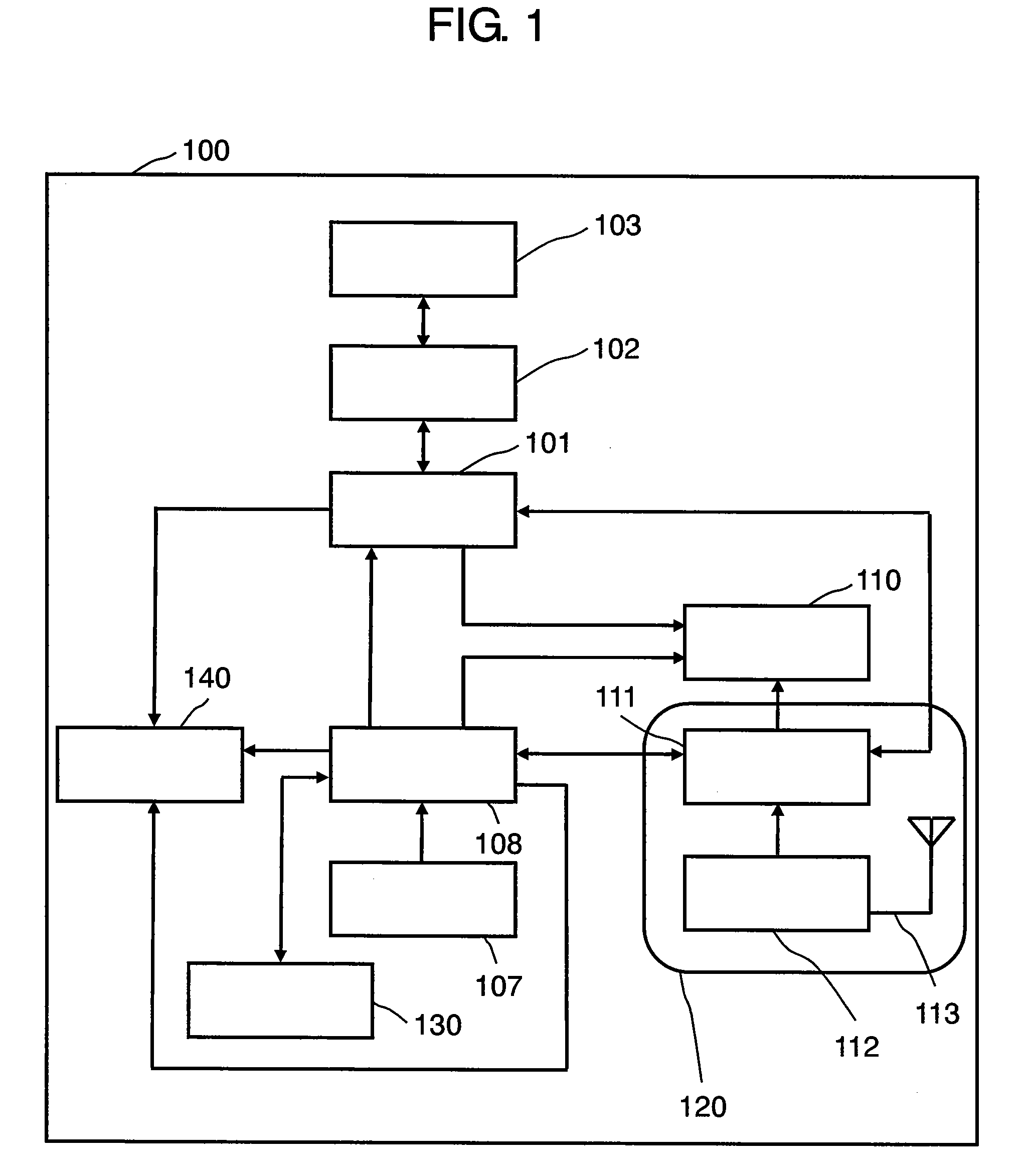
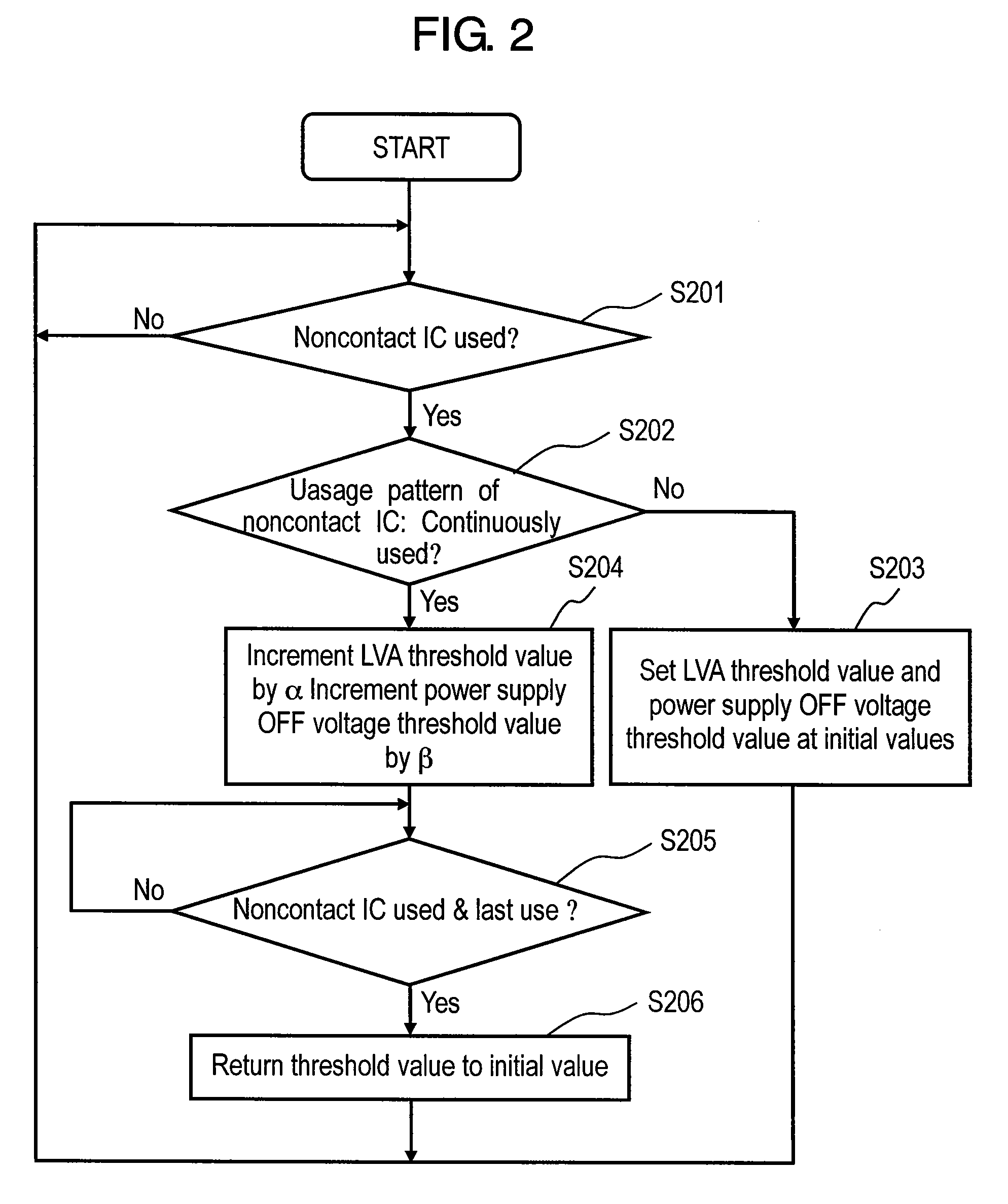
[0038]A portable terminal device of exemplary embodiment 1 will be described hereinafter with reference to the accompanying drawings. In exemplary embodiment 1, the operable time of the noncontact IC is extended, by varying a predetermined voltage for putting the portable terminal device into an LVA state and a predetermined voltage for stopping power supply to the portable phone function. Here, the former voltage is hereinafter referred to as “power supply OFF voltage threshold value”, and the latter voltage is hereinafter referred to as “LVA threshold value”.

[0039]FIG. 1 is a block diagram showing a configuration of a portable terminal device in accordance with exemplary embodiment 1. Portable terminal device 100 of exemplary embodiment 1 has noncontact IC 101, high frequency modulating / demodulating section 102, loop antenna 103, battery 107, control section 108, main display section 110, sub display section 140, radio communication section 120, and camera 130. Radio communication...

second exemplary embodiment

[0055]Exemplary embodiment 2 will be described hereinafter. A portable terminal device of exemplary embodiment 2 determines whether or not to set low power consumption mode in response to the usage pattern or the like of a noncontact IC. A basic configuration of the portable terminal device of exemplary embodiment 2 is the same as that of exemplary embodiment 1, so that description of the block diagram of embodiment 2 is omitted.

[0056]FIG. 5 is a flowchart showing an operation of the portable terminal device of exemplary embodiment 2. In exemplary embodiment 2, definition of single use, continuous use, and last use is the same as that of exemplary embodiment 1.

[0057]First, it is determined whether or not the noncontact IC has been used in step S501. When the noncontact IC has been used, the usage pattern of the noncontact IC is determined in step S502. When the usage pattern of the noncontact IC is single use, the process returns to step S501. When the usage pattern is continuous us...

third exemplary embodiment

[0062]A portable terminal device of exemplary embodiment 3 has a power supply selecting section for noncontact IC use, and can select power supply by a battery or by conversion from the alternating current received by a loop antenna to direct current.

[0063]FIG. 8 is a block diagram showing a configuration of a portable terminal device in accordance with exemplary embodiment 3. Portable terminal device 300 has noncontact IC 101, high frequency modulating / demodulating section 102, loop antenna 103, alternating-current detecting section 701, direct-current converting section 702, power supply selecting section 703, input section 704, battery 107, control section 108, display section 110, and radio communication section 120. Radio communication section 120 has radio communication control section 111, transmitting / receiving section 112, and antenna 113. Elements similar to those in portable terminal device 100 of embodiment 1 are denoted with the same reference marks, and the description...


PUM


Abstract

A noncontact IC communicates information to a read write unit that is an external terminal device. A high frequency modulating / demodulating section demodulates data that has been modulated by the read write unit using a load modulating method or the like. A loop antenna receives the data from the read write unit. A battery supplies power to the noncontact IC and the control section. The control section controls a portable phone function, and varies the battery voltage threshold value for issuing a low voltage alarm or the battery voltage threshold value for stopping power supply to the portable phone function, in a usage pattern where communication by the noncontact IC is performed twice or more.

Description

[0001]THIS APPLICATION IS A U.S. NATIONAL PHASE APPLICATION OF PCT INTERNATIONAL APPLICATION PCT / JP2006 / 301425.TECHNICAL FIELD[0002]The present invention relates to a portable terminal device, and more particularly to a portable terminal device having a noncontact IC function.BACKGROUND ART[0003]Recently, a portable terminal device having a noncontact Integrated Circuit (IC) function is proposed, and is disclosed in Japanese Patent Unexamined Publication No. 2001-223631, for example. The portable terminal device employs a noncontact IC to facilitate payment of a fare of an electric train or payment for purchase at a convenience store without delivery of cash.[0004]There are two types of noncontact IC systems having a noncontact IC function. One type is called a proximity type, and has a carrier wave frequency of 13.56 MHz used at a communication distance of tens to about 70 cm. The other type is called a close type, and has a carrier wave frequency of 4.91 MHz used at a communicatio...

Claims


Application Information

Patent Timeline
Patent Type & Authority Applications(United States)
IPC IPC(8): H04B1/38H04W52/02
CPCH04B5/0056H04B5/02H04W52/0264Y02B60/50H04W52/0277H04W52/029H04W52/027Y02D30/70H04B5/77H04B5/48
Inventor MATSUURA, IWAO
Owner PANASONIC CORP
Learn More