Rotary shaft coupling

a technology of rotary shafts and couplings, applied in the direction of yielding couplings, couplings, mechanical instruments, etc., can solve the problems of high manufacturing cost, high noise, and flexible rotary shaft couplings, and achieve superior effects, increased durability, and accurate transmission to another rotation axis

Inactive Publication Date: 2009-04-09
ENPLAS CORP
View PDF11 Cites 54 Cited by
  • Summary
  • Abstract
  • Description
  • Claims
  • Application Information

AI Technical Summary

Benefits of technology

[0027]The rotary shaft coupling of the present invention is configured and operated as described above. Therefore, even when shaft core misalignment is present between rotation axes, rotation from one rotation axis can be accurately transmitted to another rotation axis. Superior effects, such as increased durability, can be achieved without noise being generated.

Problems solved by technology

However, the rotary shaft coupling using flexible joints has disadvantages such as having a large number of components, being heavy, rotational unevenness during rotation transmission, and being high in manufacturing cost.
Therefore, a collision noise is generated, causing a loud noise.
The rotation is not transmitted smoothly, and rotational unevenness occurs.
On the other hand, when the clearance is large, impact force increases.
Moreover, when the clearance is large, a circumferential direction length of a convex section of the concave and convex section shortens, and strength of the convex section weakens.
Durability deteriorates.

Method used


Image

  • Rotary shaft coupling
  • Rotary shaft coupling
  • Rotary shaft coupling

Examples


first embodiment

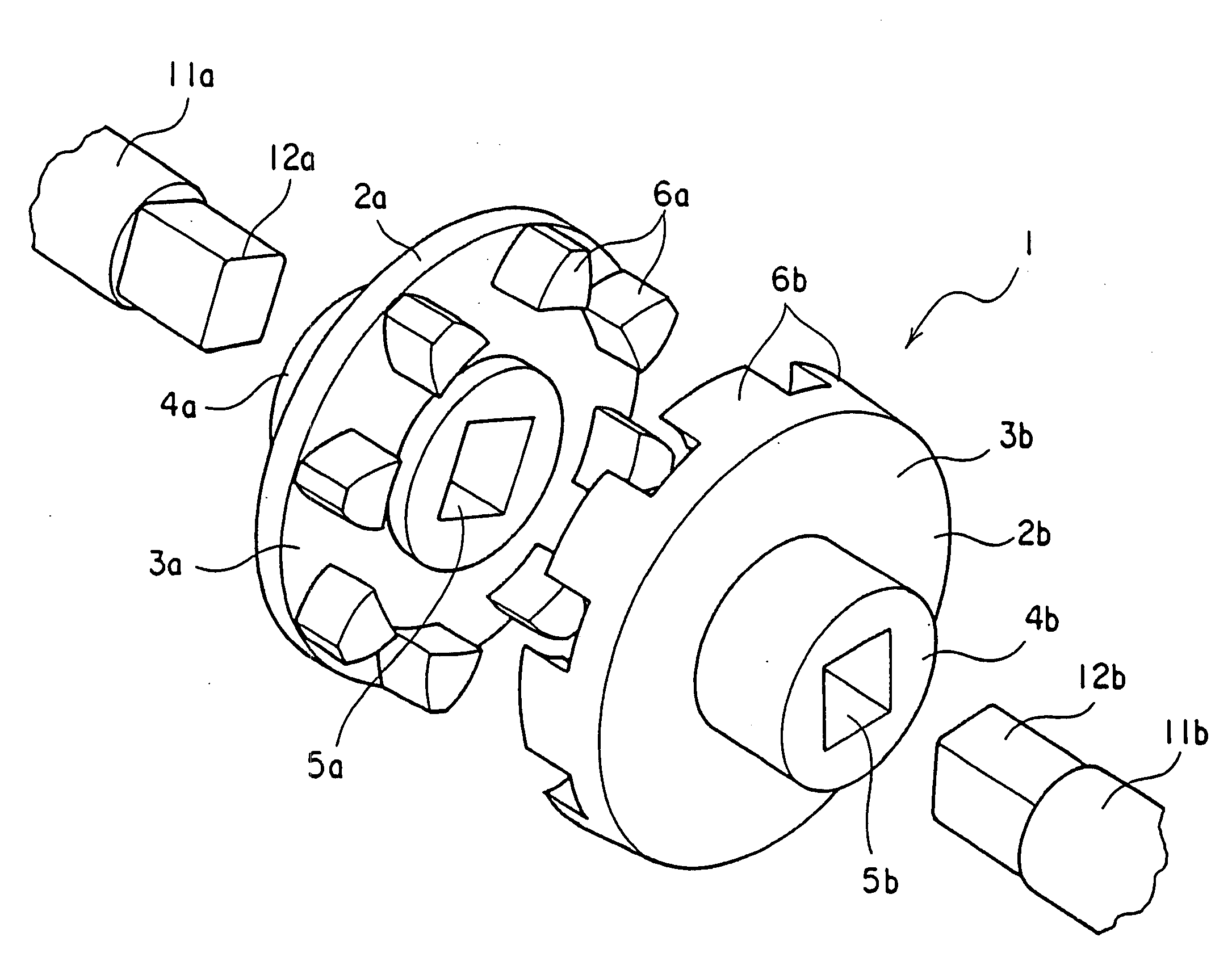
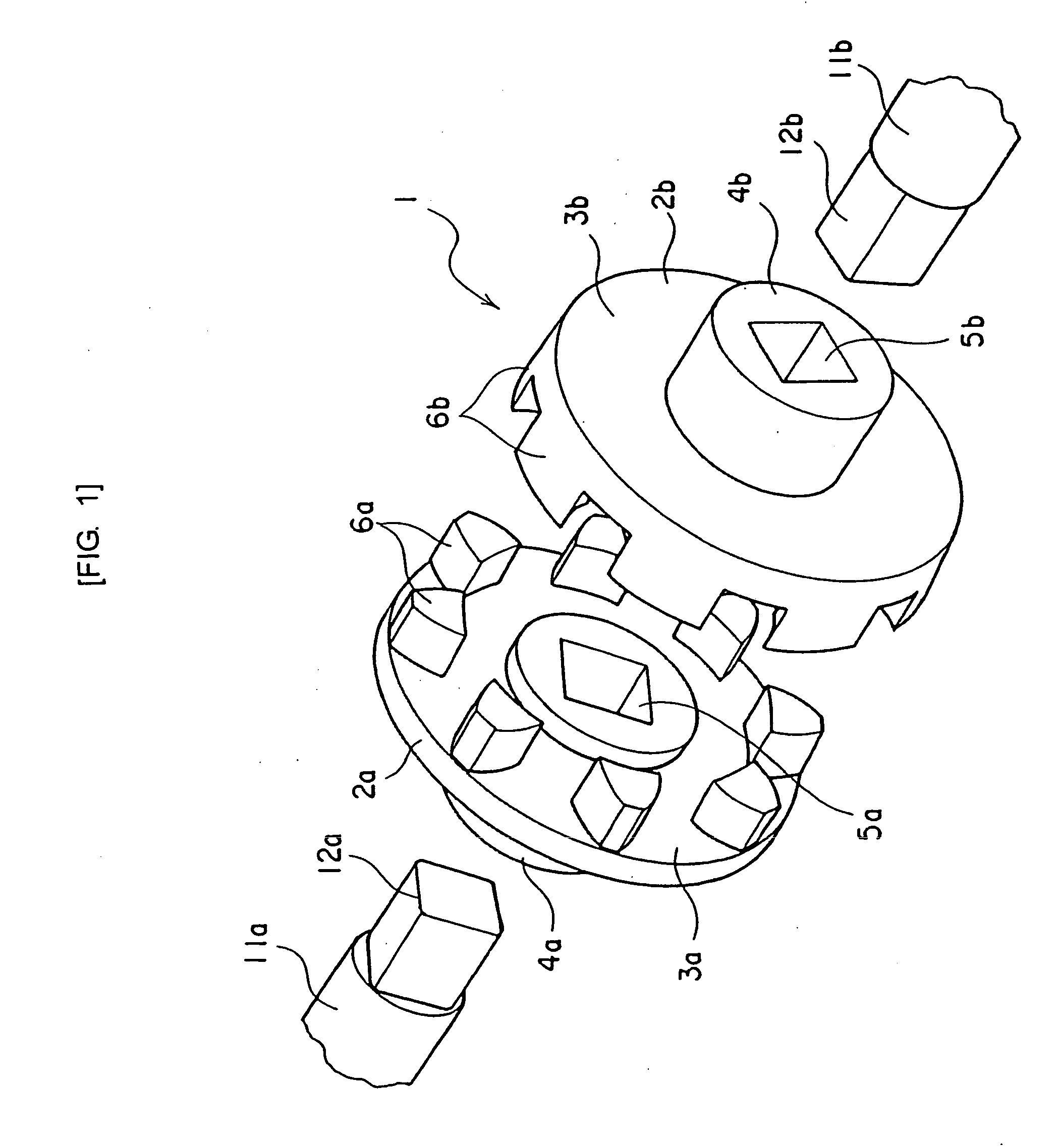
[0044]FIG. 1 to FIG. 4 are diagrams of a rotary shaft coupling according to the present invention.

[0045]As shown in the diagrams, a rotary shaft coupling 1 according to the first embodiment includes a pair of joint halves, a joint half 2a and a joint half 2b, that are respectively attached to ends of opposing rotation axis 11a and rotation axis 11b. The pair of joint halves 2a and 2b transmit rotation of one axis to the other axis. The rotary shaft coupling 1 is formed having a gear with eight teeth.

[0046]Specifically, in the joint half 2a, a boss section 4a is formed in a center of a disc-shaped main body 3a. A center hole 5a having a rectangular cross-section is formed on the boss section 4a. The center hole 5a fits with an axial end section 12a of a rotation axis 11a in a serrated manner. The axial end section 12a has a rectangular cross-section. In the joint half 2b, a boss section 4b is formed in a center of a disc-shaped main body 3b. A center hole 5b having a rectangular cros...

third embodiment

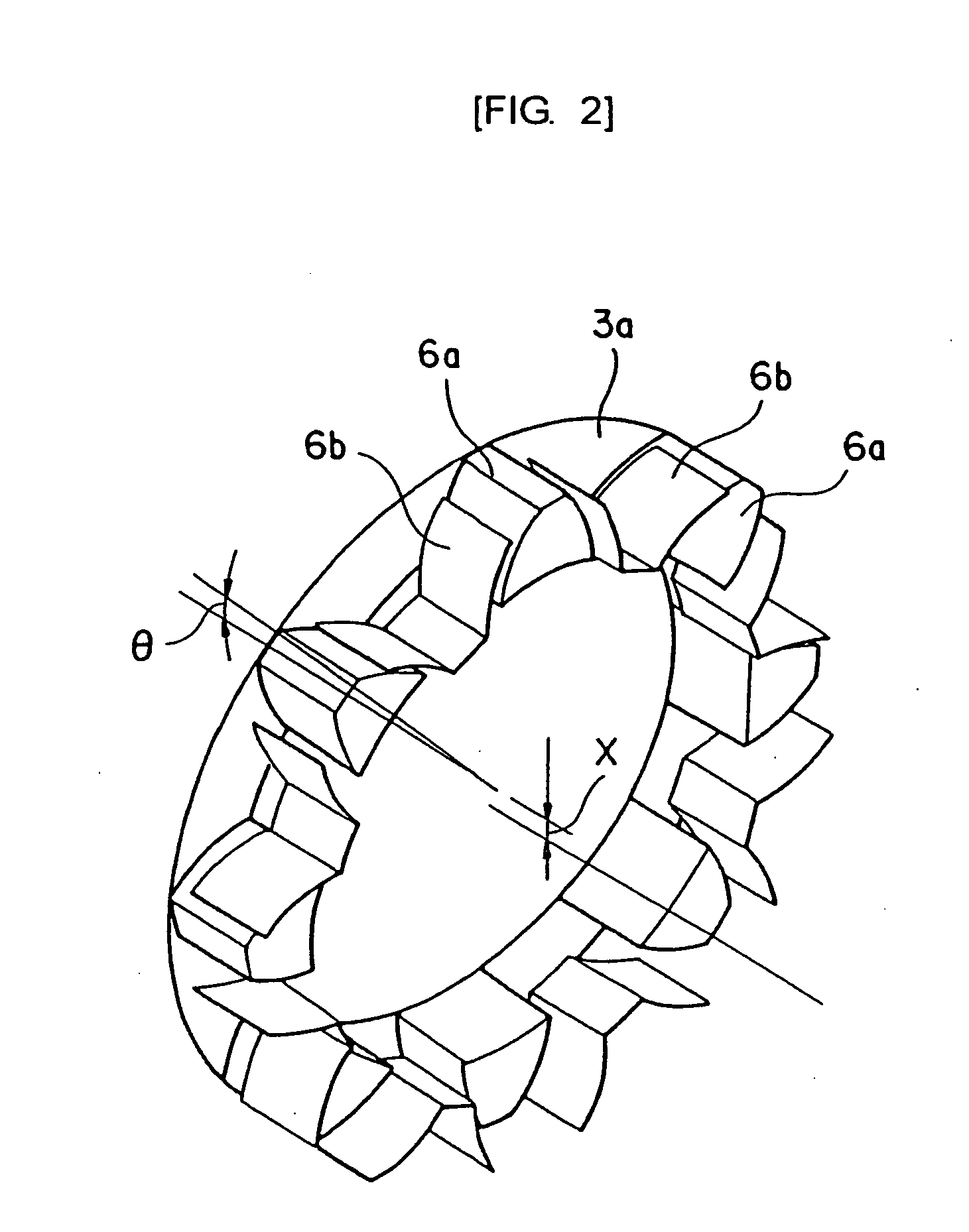
[0048]FIG. 7 and FIG. 8 show a gear form having six teeth according to another embodiment (third embodiment). The outer teeth 6a are formed connected to the boss section 4a and projecting from the main body 3a. The inner teeth 6b are formed by lightening cuts being made on the main body 3b from the boss section 4b section. Several lightening cuts 9 are also formed in required areas. Other configurations are similar to that according to the embodiment shown in FIG. 5 and FIG. 6.

[0049]Next, operations according to the embodiment will be described.

[0050]A meshing state between the outer teeth 6a and the inner teeth 6b will be described with reference to FIG. 9 and FIG. 10 showing the rotary shaft coupling 1 having a six-tooth gear form (third embodiment).

[0051]The joint half 2a and the joint half 2b of the rotary shaft coupling 1 according to the embodiment (third embodiment) in which the gear form has six teeth mesh and transmit rotation as shown in FIG. 9. FIG. 9 shows a state in whi...

fourth embodiment

[0058]As shown in FIG. 11 and FIG. 12, an arc-shaped spring 13 can be mounted between a pin 14a and a pin 14b to allow the outer teeth 6a of the joint half 2a and the inner teeth 6b of the joint half 2b of the rotary shaft coupling 1 to always mesh. The pin 14a projects from the main body 3a of the joint half 2a. The pin 14b projects from the main body 3b of the joint half 2b. A force rotating the main body 3a and the main body 3b in mutually opposite directions is applied by elasticity of the spring 13. As a result, the outer teeth 6a and the inner teeth 6b always mesh at tooth flanks on one side in the circumferential direction.


PUM


Abstract

A rotary shaft coupling is provided that can accurately transmit rotation of one rotation axis to another rotation axis even when shaft core misalignment is present between the rotation axes, and has superior durability, without generating noise.In a rotary shaft coupling 1 including a pair of joint halves 2a and 2b that are respectively attached to opposing axial end sections 12a and 12b and transmit rotation of one axis 11a to another axis 11b, outer teeth 6a of a gear are provided on one joint half 2a and inner teeth 6b that mesh with the outer teeth 6a and have a same number of teeth as the outer teeth 6a are provided on the other joint half 2b. Each outer tooth 6a and each inner tooth 6b are formed to absorb shaft core misalignment between both axes 11a and 11b and perform rotation transmission by having an involuted tooth profile of a same module and a tooth flank of the involuted tooth profile displaced in a circumferential direction.

Description

BACKGROUND OF THE INVENTION[0001]1. Field of the Invention[0002]The present invention relates to a rotary shaft coupling. In particular, the present invention relates to a rotary shaft coupling that is suitable for transmitting rotation between rotational axes disposed such that axial ends oppose each other.[0003]2. Description of the Related Art[0004]In general, a rotary shaft coupling is used to smoothly transmit rotation between rotational axes of which shaft cores may be opposing each other in a misaligned state.[0005]Conventionally, there is a rotary shaft coupling that uses flexible joints. However, the rotary shaft coupling using flexible joints has disadvantages such as having a large number of components, being heavy, rotational unevenness during rotation transmission, and being high in manufacturing cost.[0006]Therefore, a following rotary shaft coupling is proposed (refer to, for example, Patent Literature 1). The rotary shaft coupling has a pair of joints having a same s...

Claims


Application Information

Patent Timeline
Patent Type & Authority Applications(United States)
IPC IPC(8): F16D3/18
CPCF16D3/04F16D3/02F16D3/18
Inventor KAJIWARA, YASUSHISUZUKI, YASUHIRO
Owner ENPLAS CORP
Why Eureka
Try Eureka