Chain noise reduction device

a noise reduction device and chain technology, applied in the direction of belts/chains/gearings, gearing elements, hoisting equipment, etc., can solve the problems of chain rollers or links contacting the sprocket, excessive noise and excessive wear, and rapid wear, so as to reduce the level of chain engagement noise, reduce wear, and increase the life of resilient materials

Inactive Publication Date: 2009-04-09
BORGWARNER INC
View PDF11 Cites 24 Cited by
  • Summary
  • Abstract
  • Description
  • Claims
  • Application Information

AI Technical Summary

Benefits of technology

[0015]A cushion ring is received in a concentric groove in a sprocket with teeth and a hub. More specifically, the groove is defined between an annular portion of the hub and the teeth, for contacting link chain strands of a chain. The cushion ring has an inner ring and an outer ring. The outer ring is made of an incompressible material that has a load bearing area for receiving the load from links o

Problems solved by technology

One difficulty associated with such chain and sprocket arrangements is the impact of the chain rollers or links on the sprocket as they engage.
This impact creates excessive noise and excessive wear.
However, because of the f

Method used


Image

  • Chain noise reduction device
  • Chain noise reduction device
  • Chain noise reduction device

Examples


first embodiment

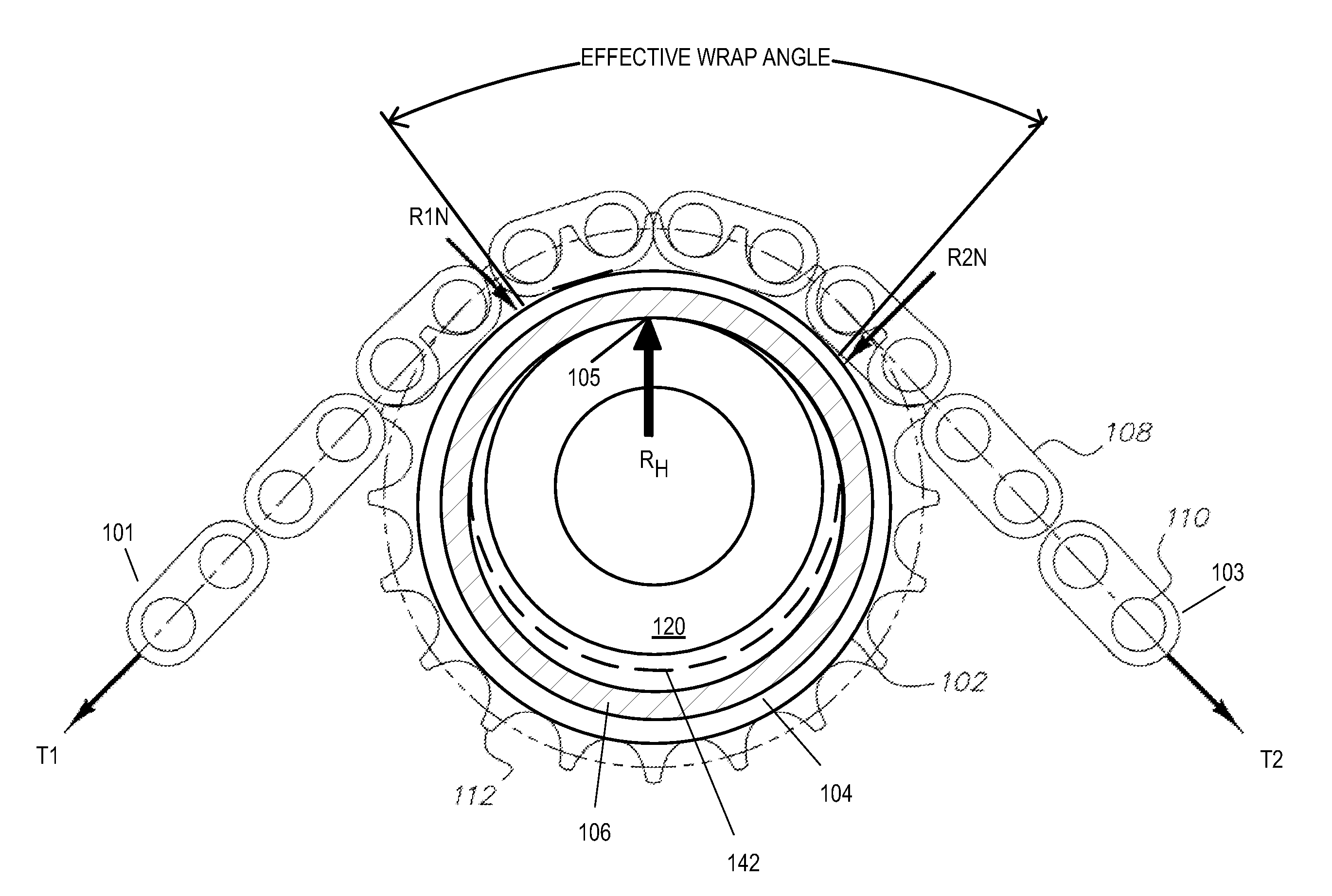
[0039]FIGS. 11 and 13 show another schematic of a cushion ring of the first embodiment with a sprocket. The sprocket comprises a hub 120, an annular portion with radial flanges 114 and a continuous circumferential row of spaced apart radially projecting teeth 112. The annular portion is fastened or welded onto the hub 120 and the radial flanges 114 define circular outer diameters or concentric grooves 118 that are larger than the cushion ring inner diameter, trapping the cushion ring 102 loosely within the concentric groove 118. The grooves 118 are positioned coaxially with the sprocket 112 and are adjacent to the sprocket teeth 112a. A small space 107 (see FIG. 10) is present between the groove 118 and the resilient inner ring 106 of the cushion ring 102 to allow the resilient component of the inner ring 106 to displace as necessary. The links 108 of chain run along the outer surface or load bearing portion 104a of the outer ring 104.

second embodiment

[0040]FIGS. 14 and 15 show a cushion ring of a second embodiment with a sprocket. The cushion ring 202 is comprised of an outer ring 204 made of spring-like steel that is not compressible and an inner ring 206 made of a resilient material such as rubber or plastic. In this embodiment, the outer ring 204 and the inner ring 206 are not bonded together and are independent of each other or separate. The inner ring 206 has a smaller diameter than the outer ring 204 and a space 207 is present between the inner ring 206 and the outer ring 204. The inner ring 206 is preferably an O-ring. The sprocket comprises a hub 120, an annular portion with radial flanges 114 and a continuous circumferential row of spaced apart radially projecting teeth 112a. The annular portion is fastened or welded onto the hub 120 and the radial flanges 114 define circular outer diameters or concentric grooves 218 that are larger than the cushion ring inner diameter, trapping the cushion ring 202 loosely within the c...


PUM


Abstract

A cushion ring (102) is received in a concentric groove in a sprocket (112) with teeth and a hub. More specifically, the groove is defined between an annular portion of the hub and the teeth. The cushion ring has an inner ring (106) and an outer ring (104). The outer ring is made of an incompressible material that has a load bearing area for receiving load from the links of the chain. The load and engagement noise energy of the chain links are combined and distributed over a large area of the outer ring. The inner ring receives this distributed load and noise energy from the outer ring and absorbs most of such energy. This improved distribution decreases wear and increases life of the resilient material while also providing for a reduced level of chain engagement noise.

Description

REFERENCE TO RELATED APPLICATIONS[0001]This application claims an invention which was disclosed in Provisional Application No. 60 / 784,431, filed Mar. 21, 2006, entitled “CHAIN NOISE REDUCTION DEVICE”. The benefit under 35 USC §119(e) of the United States provisional application is hereby claimed, and the aforementioned application is hereby incorporated herein by reference.BACKGROUND OF THE INVENTION[0002]1. Field of the Invention[0003]The invention pertains to the field of chain noise reduction devices. More particularly, the invention pertains to cushion or damping rings in chain sprockets.[0004]2. Description of Related Art[0005]Chains and sprockets have long been used as a means for transmitting power, timing rotary components and the like. One difficulty associated with such chain and sprocket arrangements is the impact of the chain rollers or links on the sprocket as they engage. This impact creates excessive noise and excessive wear. This impacting and the noise associated th...

Claims


Application Information

Patent Timeline
IPC IPC(8): F16H55/30
CPCF16H2055/306F16H55/30
Inventor MARKLEY, GEORGE L.MAXSON, TIMOTHY J.CHEKANSKY, JASON W.
Owner BORGWARNER INC
Why Eureka
Try Eureka