
Chronic total occlusion (CTO) removal device

a total occlusion and removal device technology, applied in the field of occlusion removal devices, can solve the problems of difficult removal of ctos, non-uniform ctos and other occlusions, pain or life-threatening to a human patient or an animal, and achieve the effect of reducing increasing the effective stiffness of the device, and allowing the loop to be varied

Inactive Publication Date: 2009-04-09
COOK INC
View PDF9 Cites 27 Cited by
  • Summary
  • Abstract
  • Description
  • Claims
  • Application Information

AI Technical Summary

Benefits of technology

"The invention is a device for treating blockages in blood vessels. It consists of a catheter and a longitudinal inner component that can be moved relative to the catheter. The inner component has a looped element that can be extended or retracted to change the stiffness of the device. By adjusting the position of the catheter and inner component, the device can be adapted for different regions of a blockage. It can be used to remove partial blockages and is particularly suitable for treating chronic total occlusions. The device has an opening to aspirate debris or allow fluid to be effused to the blockage. The distal opening of the catheter has keys to shape the loop as it emerges from the opening. This device provides greater flexibility and precision for treating blockages in blood vessels."

Problems solved by technology

Such blockages can be either total or partial and can be painful or life threatening to a human patient or to an animal.
CTOs often have a fibrous cap that makes removal of CTOs difficult as the cap prevents entry of a removal device into the softer underlying plaque material.
CTOs and other occlusions, whether partial or total, are often non-uniform.
A problem with some prior art devices is that if the device is suitable for cutting through the tough cap then the device will too easily cut through the softer inner, and there is the risk of a surgeon inadvertently damaging the interior lining of the blood vessel.
On the other hand, if a prior art device is suitable for cutting thought the soft inner of a CTO then the device will often be unsuitable for cutting through the tough cap.

Method used


Image

  • Chronic total occlusion (CTO) removal device
  • Chronic total occlusion (CTO) removal device
  • Chronic total occlusion (CTO) removal device

Examples


Embodiment Construction

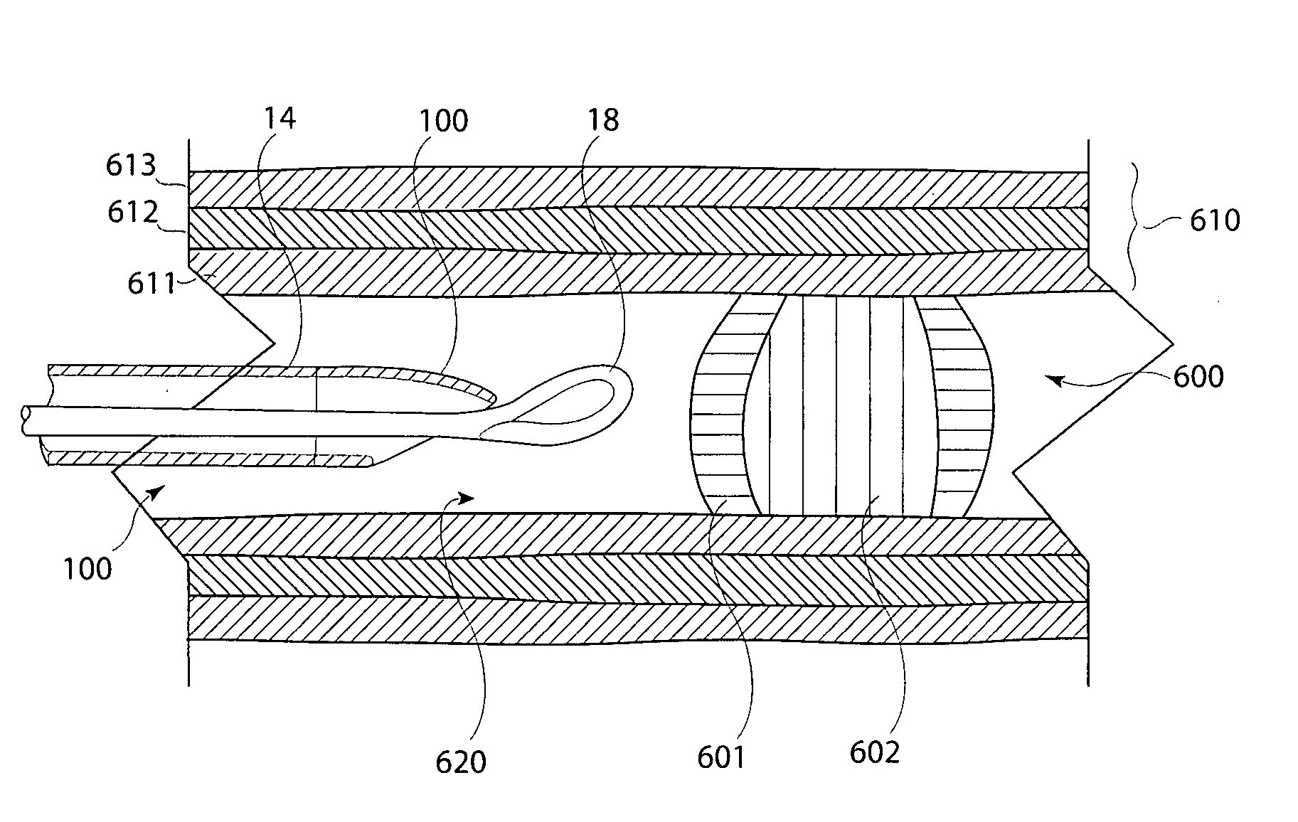
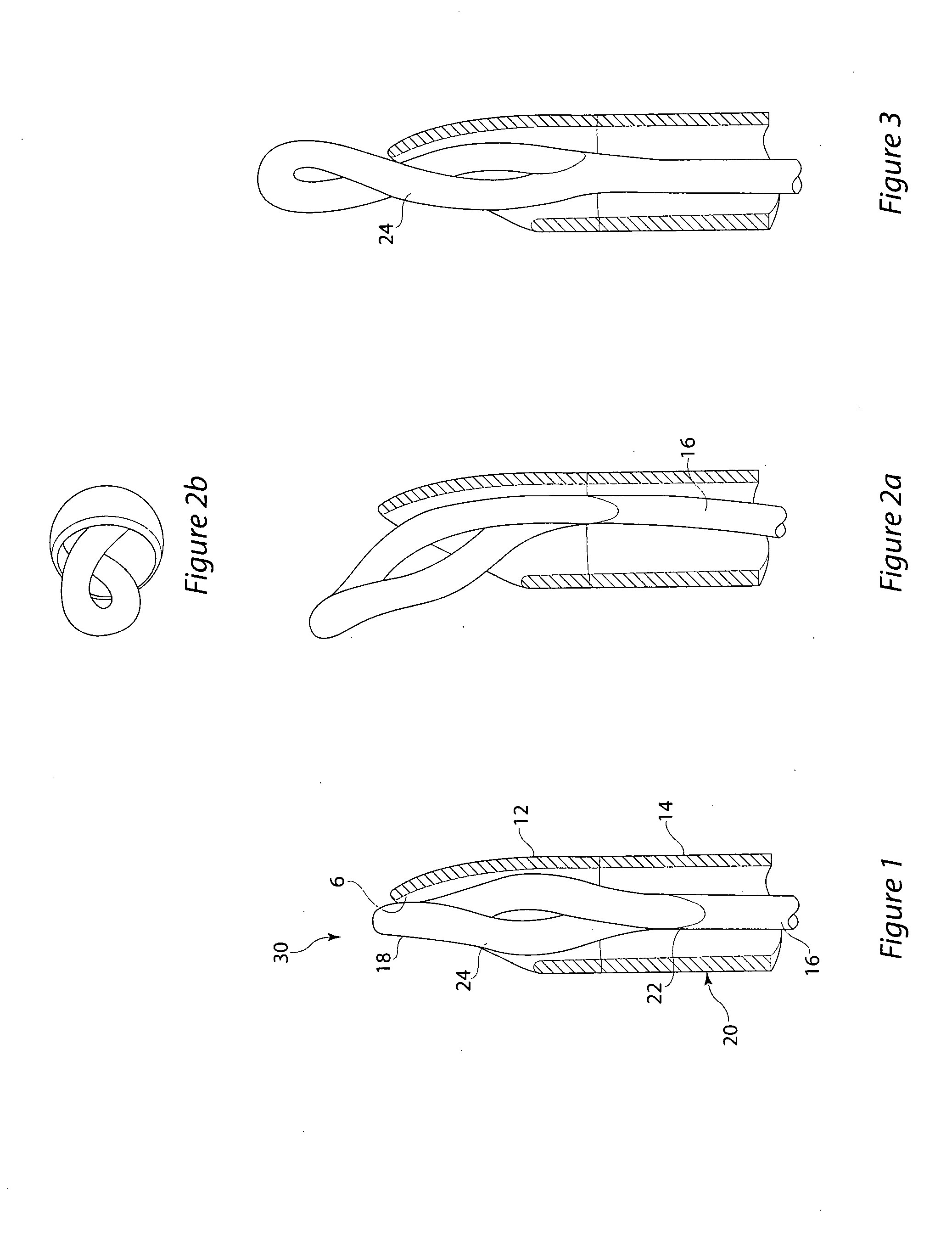
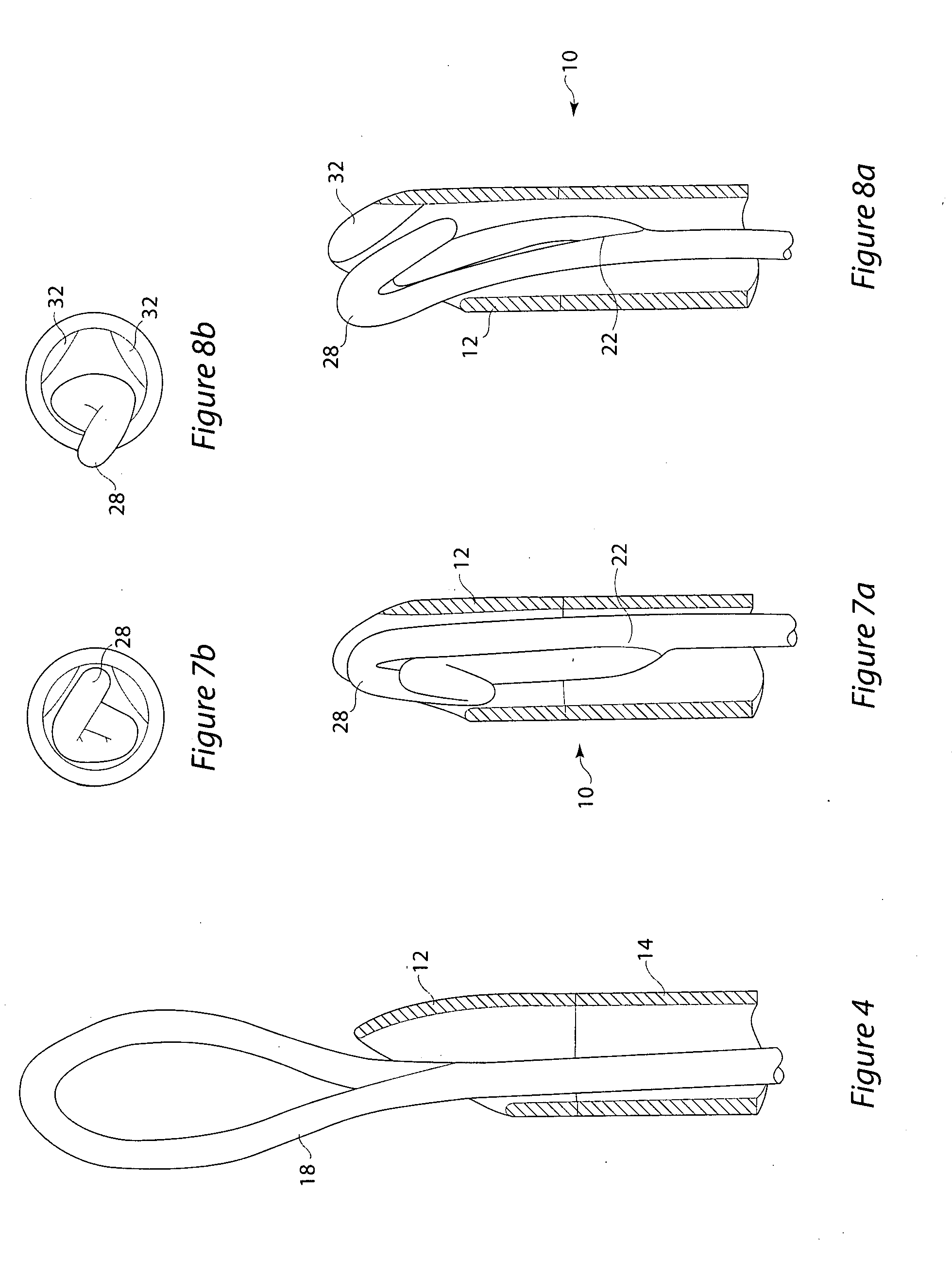
[0028]FIGS. 1 to 6 show a distal end 100 of an occlusion removal device 10 comprising a catheter 20 and an inner component 30. The catheter 20 comprises a metallic, radiopaque, distal opening 12 and a polymeric catheter sheath 14. More generally, the distal opening 12 and the catheter sheath 14 may be formed from other materials (as opposed to a metallic distal opening 12 and a polymeric catheter sheath 14). In alternative embodiments, the distal opening is non-metallic and is provided with one or more radiopaque markers (not shown but of a type common in the art).

[0029]As shown particularly by FIGS. 1 to 4, the tip of the distal end 100 of the catheter 30 is pre-curved. By pre-curved, it is meant that the distal end 100 of the catheter 20 is curved at the time of manufacture or final formation and thus before the catheter 20 is inserted into a body lumen. The pre-curved portion may be adjacent to the distal opening 1, or may include the distal opening 1. The degree of curvature may...


PUM


Abstract

There is disclosed a device for removing chronic total occlusions (CTO) from blood vessels or other body lumens. In one embodiment the device has a loop at a distal end connected by a shaft to a proximal end. The shaft is provided inside a catheter that has an opening at the distal end and a handle at the proximal end. By manipulating the position of the loop relative to the opening, the effective stiffness of the loop may be changed. This allows a physician to vary the loop stiffness so as to be appropriate with regard to the toughness of a CTO (some CTOs have a relatively tough exterior but a relatively soft interior). The loop may have a single turn or may comprise two or more turns.

Description

TECHNICAL FIELD[0001]The present invention relates to occlusion removal devices and methods for removing deposits and / or blockages from blood vessels or other body lumens. In particular, but not exclusively, the present invention relates to the removal of Chronic Total Occlusions (CTOs).BACKGROUND OF THE INVENTION[0002]Body lumens, such as blood vessels or the ureter, can be obstructed by blockages such as CTOs or kidney stones, for example. Other types of blockages include polyps or cysts. Such blockages can be either total or partial and can be painful or life threatening to a human patient or to an animal.[0003]In blood vessels, CTOs are blockages that completely obstruct the flow of blood through the blood vessel. CTOs often have a fibrous cap that makes removal of CTOs difficult as the cap prevents entry of a removal device into the softer underlying plaque material.[0004]U.S. Pat. No. 5,792,157 discloses an intravascular occlusion material removal device for removing vascular ...

Claims


Application Information

Patent Timeline
Patent Type & Authority Applications(United States)
IPC IPC(8): A61B17/22
CPCA61B17/32056A61B17/3207A61B17/320708A61B17/320725A61B2017/320741A61B2017/22042A61B2017/22094A61B2017/2212A61B2017/320733A61B2017/22001
Inventor MELSHEIMER, JEFFRY S.URBANSKI, JASON
Owner COOK INC
Learn More