Machine-Independent Roller Counting System

a counting system and machine-independent technology, applied in the field of rolling machine and method, can solve the problems of reducing the clearance by a determinable amount, reducing the cost of engraving rotary dies, and comparatively more expensive engraved rotary dies

Inactive Publication Date: 2009-04-09
GLASS JAMES +1
View PDF7 Cites 16 Cited by
  • Summary
  • Abstract
  • Description
  • Claims
  • Application Information

AI Technical Summary

Benefits of technology

[0012]The non-volatile memory and the processor are preferably resident on a single microcontroller semiconductor integrated circuit. The power use manager operates the processor in a high consumption state when the sensor passes near the anvil roller but resets to a substantially zero power consumption prior to and subsequent to detection of the anvil roller.

Problems solved by technology

Although there are various rotary die systems that rely on replaceable cutting elements removably attached to the die cylinder, more demanding applications rely on engraved, solid cutting dies.
Engraved rotary dies are comparatively more expensive and a different cylinder is required for each cutting label pattern.
Die blades are susceptible to damage and wear and in normal conditions, are repeatedly resharpened.
Compression of the bearers displaces the blade tips of the roller die slightly but measurably, and reduces the clearance by a determinable amount.
The use of higher loading forces is known to increase wear and reduce overall die life.
Maintenance of cutting die inventories and the related task of scheduling die reprocessing are significant challenges for press operators.
For example, a culling die needed for an infrequently run printing job may be drawn from storage and found to be too dull to complete the run.
Even a rushed resharpening of the cutting dies which is usually provided by third-parties, may not allow the press operator to meet a shipment deadline.
In addition, wear based failure of a cutting die during a run can result in significant lost material.
Both of these approaches reduce overall efficiency.
These manual systems are generally unreliable, however.
Press operators often fail altogether to record usage data, and when such information is recorded, the data format varies according to operator preference and press controller electronics.

Method used


Image

  • Machine-Independent Roller Counting System
  • Machine-Independent Roller Counting System
  • Machine-Independent Roller Counting System

Examples


Embodiment Construction

[0022]The invention disclosed herein is, of course, susceptible of embodiment in many different forms. Shown in the drawings and described here in detail are preferred embodiments of the invention. It is to be understood, however, that the present disclosure is an exemplification of the principles of the invention and does not limit the invention to the illustrated embodiments.

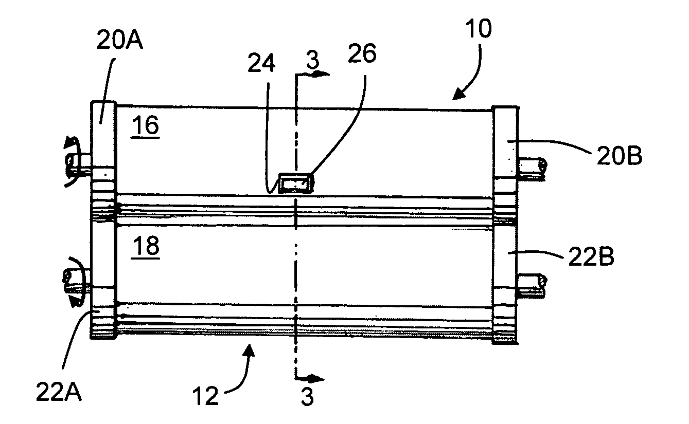
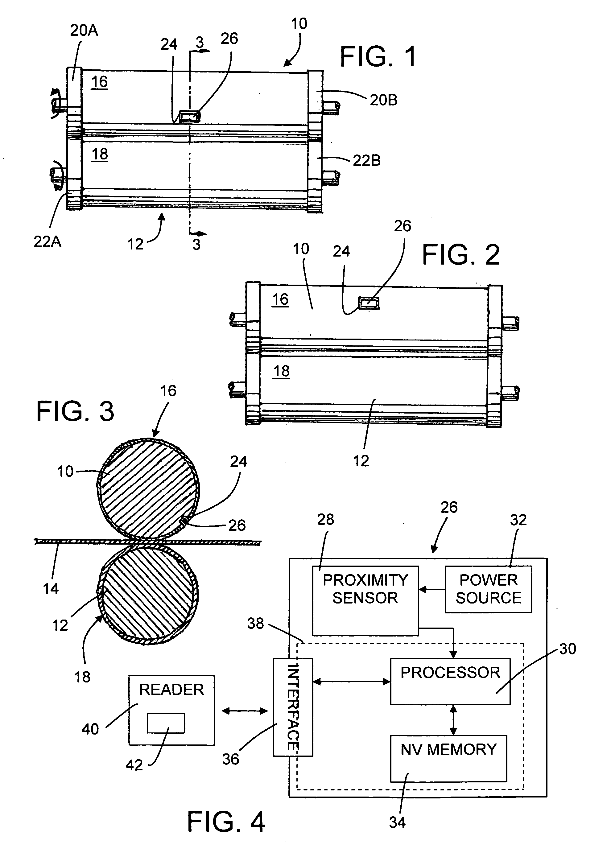
[0023]Turning now to the drawings wherein common reference numbers refer to like and corresponding elements throughout the several diagrams, a rotary cutting apparatus is shown in FIGS. 1 through 3 including a rotary cutting die 10 and an anvil roller 12. Cutting die 10 and anvil roller 12 are each mounted for rotation about their respective longitudinal axes and cooperating with one another for the die cutting of a web 14 passing therebetween. Cutting die 10 has a die cutting surface 16 thereon either spaced from or in interference with anvil surface 18. The clearance between die cutting surface 16 and anvil ...


PUM

PropertyMeasurementUnit
reset speedaaaaaaaaaa
non-volatile memoryaaaaaaaaaa
power consumptionaaaaaaaaaa

Abstract

Roller cutting die comprises a body with substantially cylindrical outer surface defining a cutting pattern extending outwardly from the surface and a recess. Secured within the recess is a data recorder sensor module adapted to count rotations past the anvil roller. The sensor module includes an electromagnetic proximity sensor for generating a signal responsive to passage near the anvil roller, a processor coupled to the proximity sensor, a power use manager at least partially defined by the processor and the proximity sensor, and a power source for the processor and the sensor. A count of rotations is stored in a substantially non-volatile memory coupled to the processor.

Description

FIELD OF THE INVENTION[0001]The present disclosure is generally directed to roller based machines and methods, and more particularly to engraved roller cutting dies.BACKGROUND OF THE INVENTION[0002]Rotary (or roller) die cutting subsystems are typically a down stream part of what is called a rotary press structure, a number of versions of which are widely available. A rotary cutting die is typically a rigid cylindrical body having a cutting blade of a fixed pattern that protrudes outwardly to a uniform distance from the cylindrical circumference. The ultimate edge of the blade pattern either contacts or nearly contacts an adjacent anvil roller, which is typically a smooth, hard, metallic cylinder. The system includes mechanisms for driving the roller die and anvil synchronously, and a structural restraint or frame portion. The sheet material intended to be cut into the pattern defined by the blade passes between the roller cutting die and the anvil. Though individual, pre-cut sheets...

Claims


Application Information

Patent Timeline
Patent Type & Authority Applications(United States)
IPC IPC(8): B26F1/44B26F1/38B26D1/12G06F19/00
CPCB26D5/00B26F1/384B26D7/28Y10T83/9372
Inventor GLASS, JAMESRIEDER, JOSH
Owner GLASS JAMES
Why Eureka
Try Eureka