Apparatus and method for suppressing dynamic pressure instability in bleed duct

a gas turbine engine and dynamic pressure instability technology, applied in the field of apparatus and methods for suppressing dynamic pressure instability in bleed ducts of gas turbine engines, can solve the problems of unacceptably high dynamic pressure oscillation, significant structural damage to the surfaces on which dynamic pressure loading occurs, and the bleed duct may become dynamically unstable and undergo pressure oscillations of high magnitude, so as to achieve the effect of suppressing dynamic pressure instability

Active Publication Date: 2009-04-16
GENERAL ELECTRIC CO
View PDF10 Cites 22 Cited by
  • Summary
  • Abstract
  • Description
  • Claims
  • Application Information

AI Technical Summary

Benefits of technology

[0010]The above mentioned needs are met by this invention, which in one aspect provides an apparatus and method for suppressing dynamic pressure instability in a bleed duct of a gas turbine engine that includes a flow diverter positioned adjacent an inlet of the bleed duct. The flow diverter is configured to prevent a flow of air in the fan bypass duct of the gas turbine engine from entering the inlet of the bleed duct when a flow control valve disposed within the bleed duct is closed, and to permit a portion of the flow of air to enter the inlet and pass through the bleed duct when the flow control valve is opened.

Problems solved by technology

When the valve is closed (or the amount of air leaking through the valve is sufficiently small) and air is flowing at a high rate through the fan bypass duct past the inlet of the bleed duct, the bleed duct may become dynamically unstable and undergo pressure oscillations of high magnitude.
Dynamic pressure levels as high as 1.125 kg / cm (16 psi) peak-to-peak at a characteristic (i.e. natural) frequency have been observed, which can cause significant structural damage to the surfaces on which the dynamic pressure loading occurs.
During certain modes of engine operation, a portion of the air flow through the fan bypass duct is routed directly into the inlet of the bleed duct such that high magnitude pressure oscillations result when the flow control valve is closed, or is leaking an insufficient amount of air.
Recent engine operational requirements, however, do not permit valve leakage, and therefore, can cause unacceptably high dynamic pressure oscillations.
In turn, the high dynamic pressure oscillations result in sonic fatigue damage and the failure of structural parts subjected to increased dynamic pressure loading, such as the surface of the bleed duct.
A second dynamic pressure instability mechanism that also results in acoustic resonances occurs when the air flow through the fan bypass duct grazes tangentially over the inlet of the bleed duct as opposed to entering the inlet directly.

Method used


Image

  • Apparatus and method for suppressing dynamic pressure instability in bleed duct
  • Apparatus and method for suppressing dynamic pressure instability in bleed duct
  • Apparatus and method for suppressing dynamic pressure instability in bleed duct

Examples


Embodiment Construction

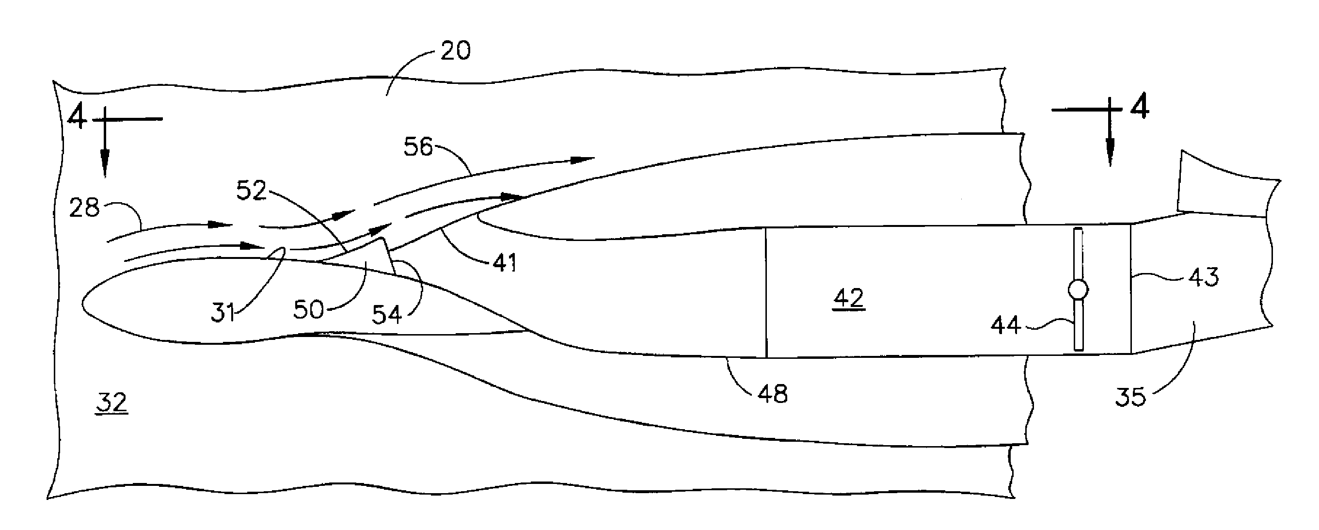
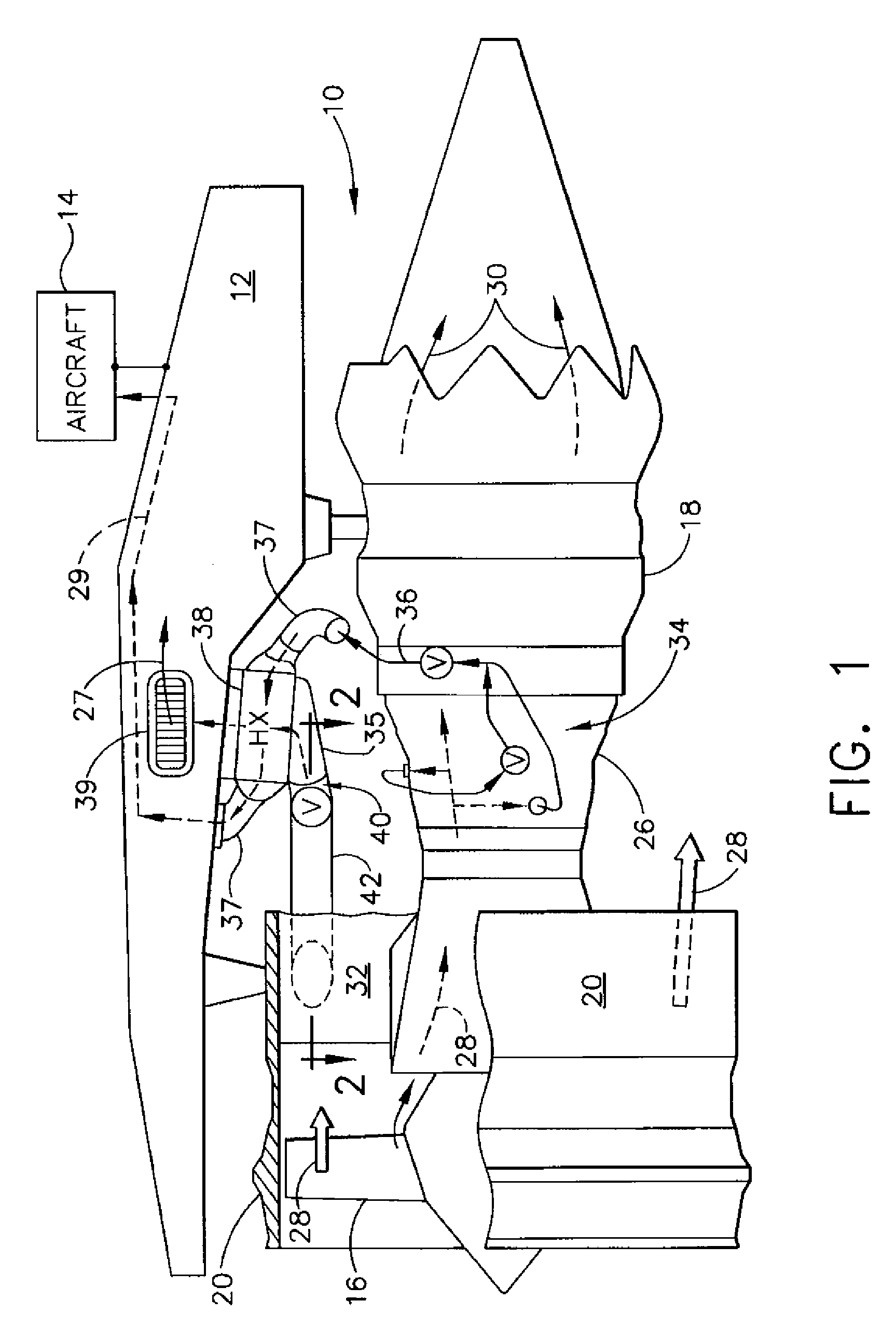
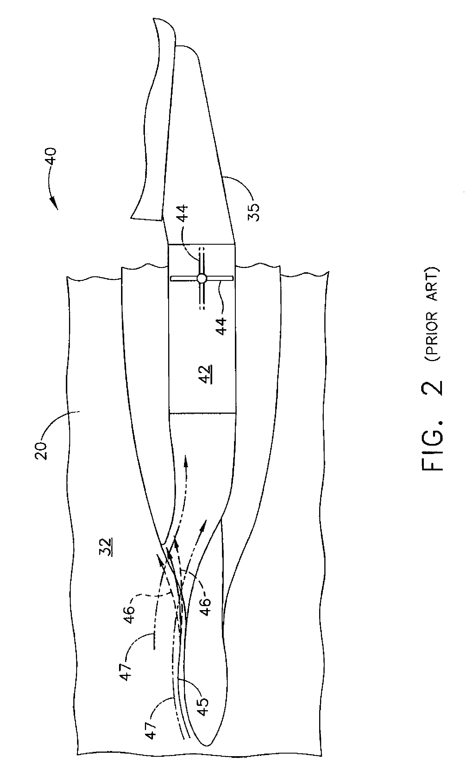
[0022]Referring to the drawings in which identical reference numerals denote the same elements throughout the different views, FIG. 1 illustrates schematically a gas turbine engine, indicated generally at 10, mounted to a support pylon 12 of an aircraft 14. The engine 10 includes a fan 16 powered by a core engine 18. The fan 16 includes a plurality of fan blades rotatably mounted within an annular fan casing 20, with the fan casing in turn mounted to the inlet end of the core engine 18 in a conventional manner. The core engine 18 includes a multistage compressor 26 having sequential stages of stator vanes and / or rotor blades that pressurize an incoming flow of air 28. The pressurized air is discharged from the compressor 26 and mixed with fuel in the combustor of the core engine 18 to generate hot combustion gases 30 that flow downstream through high pressure and low pressure turbines. The high and low pressure turbines extract energy from the combustion gases 30 prior to the gases ...


PUM


Abstract

An apparatus and method for suppressing dynamic instability in a bleed duct of a gas turbine engine includes a fan bypass duct configured to permit a flow of air through the gas turbine engine. The fan bypass duct defines a fan duct surface, and the bleed duct has an inlet in fluid communication with the fan bypass duct and a flow control valve having an opened position and a closed position. A flow diverter is positioned on the fan duct surface proximate the inlet of the bleed duct and diverts the flow of air from the inlet when the flow control valve is closed, while permitting a portion of the flow of air to enter the inlet when the flow control valve is opened.

Description

BACKGROUND OF THE INVENTION[0001]This subject matter disclosed in this application relates generally to components for gas turbine engines, and more particularly, to an apparatus and method for suppressing dynamic pressure instability in a bleed duct of a gas turbine engine.[0002]Bleed ducts on gas turbine engines extract a portion of the air from the flow path of the fan bypass duct and direct the air through a bleed duct to a heat exchanger to cool the engine. The flow of air through the bleed duct is typically controlled by a flow control valve, for example a butterfly valve. The flow control valve is closed during certain modes of engine operation, thereby preventing the flow of air through the bleed duct. When the valve is closed (or the amount of air leaking through the valve is sufficiently small) and air is flowing at a high rate through the fan bypass duct past the inlet of the bleed duct, the bleed duct may become dynamically unstable and undergo pressure oscillations of h...

Claims


Application Information

Patent Timeline
Patent Type & Authority Applications(United States)
IPC IPC(8): F02C9/18F02C7/24
CPCF02K3/06F02C6/08F05D2250/51F05D2260/213Y02T50/60
Inventor KRAFT, ROBERT EUGENEBAILEY, WILLIAM ANDREWGROLL, WILLIAM CHARLES
Owner GENERAL ELECTRIC CO
Why Eureka
Try Eureka