Inner cable for push-pull control cable and method for fabricating the same

a control cable and push-pull technology, applied in the direction of manufacturing tools, mechanical equipment, transportation and packaging, etc., can solve the problems of above described rotary steering system, increased manufacturing unit cost, and inability to manufacture inner cables, etc., to achieve the effect of improving productivity, superior durability, and easy operation of manufacturing inner cables

Inactive Publication Date: 2009-04-16
KIM YOUNG CHOONG
View PDF6 Cites 6 Cited by
  • Summary
  • Abstract
  • Description
  • Claims
  • Application Information

AI Technical Summary

Benefits of technology

[0027]Accordingly, the present invention has been made to solve the above-mentioned problems occurring in the prior art, and the present invention provides an inner cable for a push-pull control cable constituting various kinds of control systems including a steering system and a method for manufacturing the same so as to generally increase durability of the push-pull control cable and reliability of a steering system, etc., and to allow the inner cable to be easily manufactured.
[0034]According to the present invention, an inner cable for a push-pull control cable, which can show its elastic force without a thermal process and can be used for a long time due to superior durability, can be provided.
[0035]Also, a process for applying tension to a coiled wire and a thermal process, which are performed in manufacturing an inner cable for a push-pull control cable, are deleted. As a result, there is an advantage in that operations of manufacturing an inner cable are easily performed, productivity is improved, and manufacturing cost is reduced.
[0036]For example, in a case of the inner cable for a push-pull control cable according to the present invention being applied to a motor boat, a coiled wire exists on an outer surface of only a part of the core wire, the part being a section from a point of the inner cable, which is caught at a time when the inner cable is pulled with the maximum degree from an connection part with the gear-box 30 of the rotary helm 20, to a point just before a first curved section. Meanwhile, the coiled wire does not exist at a remaining part of the inner cable. Therefore, the part of the inner cable, in which the coiled wire does not exist, is flexibly operated in a curved section, and compression force transferred to a part maintaining a linear length is simultaneously reduced. As a result, frictional force of the push-pull control cable is effectively prevented so that durability and reliability of the steering system can increase.
[0037]As described above, according to the present invention, an inner cable for a push-pull control cable is improved so as to increase durability of the push-pull control cable. Also, reliability of a steering system, etc, using a push-pull control cable is generally increased, and the push-pull control cable can be easily manufactured.

Problems solved by technology

However, the conventional inner cable 40a for a push-pull control cable applied to the above described rotary steering system has a problem, which is described below.
Because of this, there is a disadvantage in that manufacturing unit cost increases, unnecessary loss is caused in transferring steering force, and reliability of and durability of a steering system is reduced.
However, the conventional inner cable 40a for a push-pull control cable has a spiral wire 42a wound on whole sections thereof so that big supporting force is unnecessarily generated at the curved section.
As a result, abrasion generated due to interference with other components is promoted so that durability and reliability are reduced.
As described above, the conventional inner cable 40a for the push-pull control cable has an economical problem and a problem in reliability as well as durability of the steering system.
However, it is very difficult to resolve such problems by using the structure of the conventional inner cable 40a for the push-pull control cable, which is illustrated in FIG. 2b, and a method for manufacturing the inner cable.
However, in the conventional inner cable 40a for a push-pull control cable, because it is impossible to wind the spiral wire 42a on only a desired part of the inner cable due to technical limitation in the above described manufacturing method, there is no choice but to wind the spiral wire 42a on the whole length of the inner cable.
Meanwhile, it can be supposed that the spiral wire 42a can be wound on only a required part (a part which is about 60 cm connected with the rotary helm) in manufacturing the conventional inner cable 40a for a push-pull control cable, but this is very difficult due to technical problems, and is also uneconomical.
Also, this is very non-efficient in an economical view.

Method used


Image

  • Inner cable for push-pull control cable and method for fabricating the same
  • Inner cable for push-pull control cable and method for fabricating the same
  • Inner cable for push-pull control cable and method for fabricating the same

Examples


Embodiment Construction

[0063]Hereinafter, an embodiment of the present invention will be described in detail with reference to FIGS. 3 and 4.

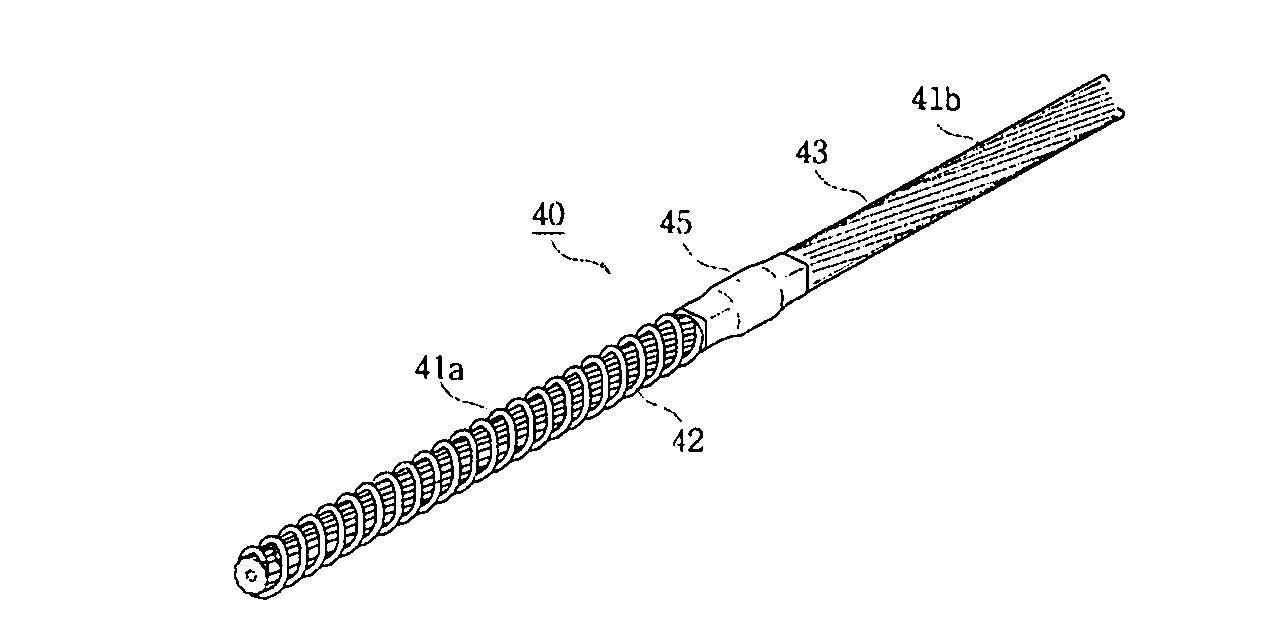
[0064]FIG. 3a is a perspective view of an inner cable for a push-pull control cable according to the present invention, FIG. 3b is an exploded perspective view of an inner cable for a push-pull control cable according to the present invention, FIG. 3c is a front view showing the assembled state of the inner cable for a push-pull control cable, which is shown in FIG. 3b, in which a connector part as a main part is shown in a sectional view, and FIG. 3d is a front view showing the assembled state of the inner cable for a push-pull control cable, which is shown in FIG. 3b, in which a connector part as a main part according to another embodiment is shown in a sectional view.

[0065]Referring to theses drawings, the inner cable 40 for a push-pull control cable according to the present invention includes: a first core wire 41a having a predetermined length, which is formed b...


PUM

PropertyMeasurementUnit
lengthaaaaaaaaaa
distanceaaaaaaaaaa
thicknessaaaaaaaaaa

Abstract

Disclosed is an inner cable for a push-pull control cable and a method for manufacturing the inner cable. The inner cable of a push-pull control cable applied to various control system including a steering system and a method for manufacturing the inner cable can generally increase durability of a control cable and reliability of a steering system, and can be easily manufactured. The inner cable includes a core wire with a predetermined length, which is formed by twisting a plurality of wire strands; a coiled wire, which is assembled with one end of the core wire in such a manner that the coiled wire winds the outer circumferential surface of the core wire in a spiral shape; and synthetic resin coating formed at a remaining part of the core wire, except for a part assembled with the coiled wire.

Description

BACKGROUND OF THE INVENTION[0001]1. Field of the invention[0002]The present invention relates to an inner cable for a control cable, and more particularly to an inner cable for a push-pull control cable which can increase durability of a push-pull control cable applied to various kinds of control system including a steering system of a marine vehicle, such as a boat, etc. and reliability of a control system employing the push-pull control cable, and also allows the push-pull control cable to be easily manufactured.[0003]2. Description of the Prior Art[0004]In general, a push-pull control cable provides a means for transferring linear motion from one position to another position.[0005]Such a push-pull control cable includes a steering system of a motor boat, etc. so as to be used for heavy equipment, such as jet skis, vehicles, fork lifts, etc., which require steering operation.[0006]Among these, a steering system of the motor boat M includes a system which converts operational force...

Claims


Application Information

Patent Timeline
Patent Type & Authority Applications(United States)
IPC IPC(8): F16C1/20B23P11/00
CPCB63H25/10D07B2501/2084Y10T29/49826F16C1/101Y10T74/20456F16C1/205D07B5/005D07B5/007D07B7/027D07B2201/1024D07B2201/2044F16C2326/30F16C1/20
Inventor KIM, YOUNG-CHOONG
Owner KIM YOUNG CHOONG
Why Eureka
Try Eureka