

Fuel supply device
a technology of fuel supply and control module, which is applied in the direction of liquid fuel feeders, machines/engines, and feed systems, etc., can solve the problems that the control module disposed inside the fuel tank may receive a strong force, and achieve the effect of reducing the cooling effect of the control modul
- Summary
- Abstract
- Description
- Claims
- Application Information
AI Technical Summary
Benefits of technology
Problems solved by technology
Method used
Image

Examples
embodiment 1
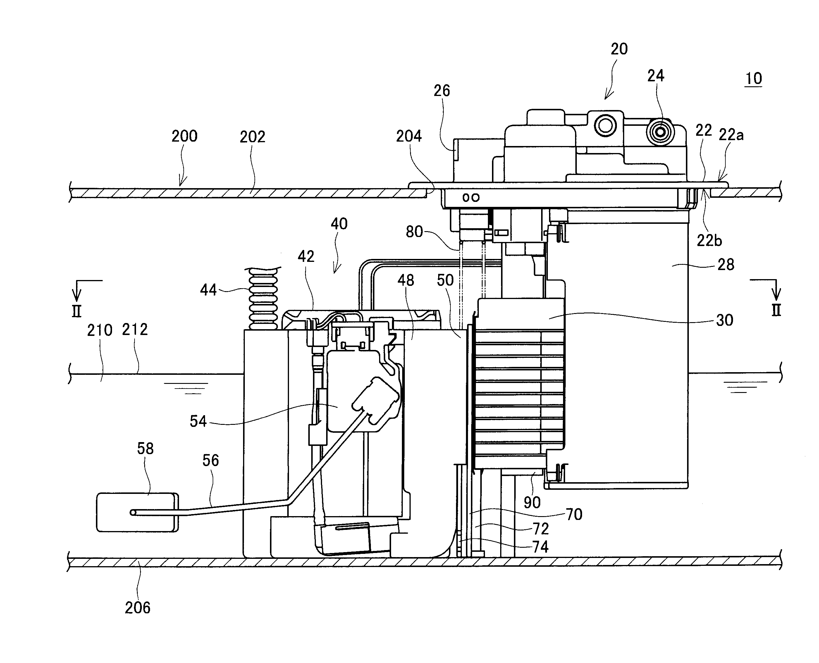
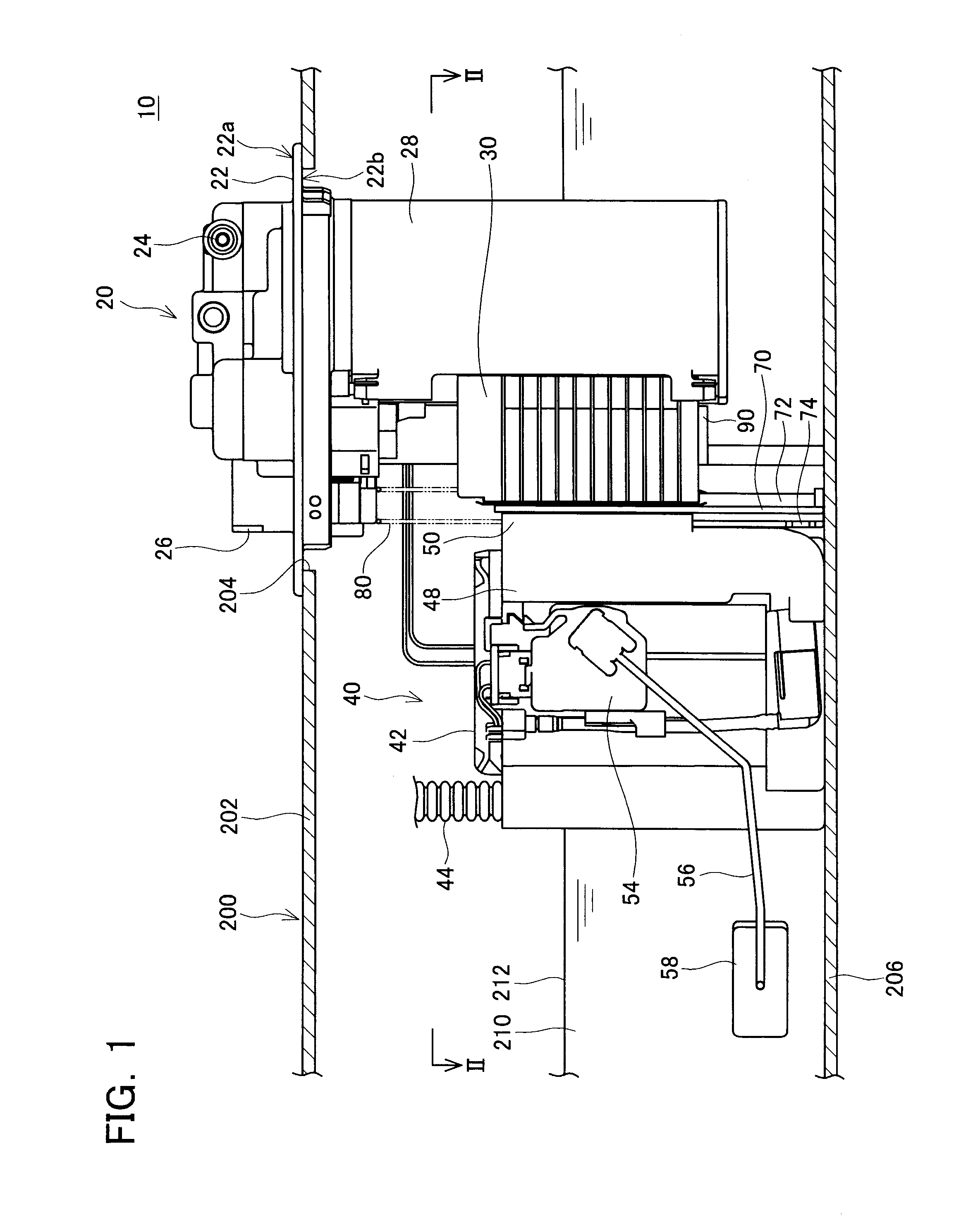
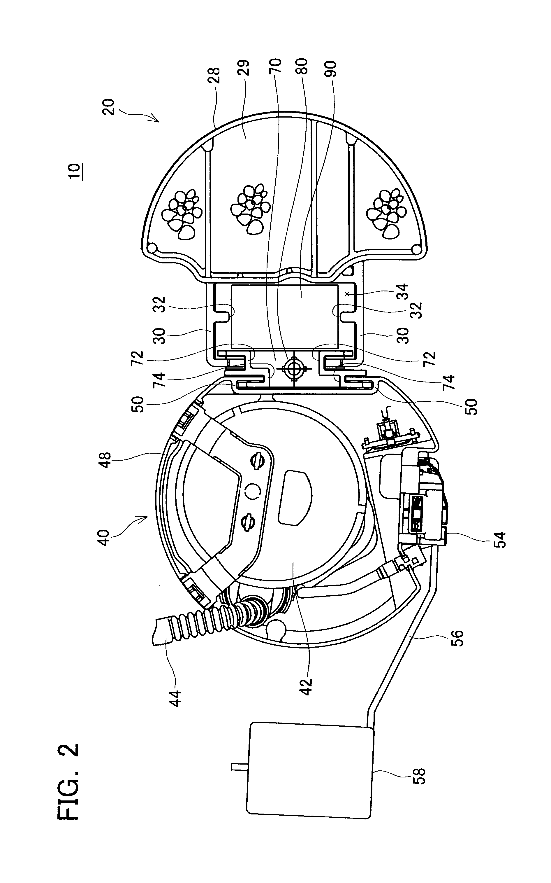
[0041]As shown in FIGS. 1 and 2, the fuel supply device 10 of Embodiment 1 is composed mainly of an upper unit 20, a lower unit 40, a coupling member 70 for coupling the upper unit 20 and the lower unit 40 to each other, and a control module 90. The control module 90 is fixed to the upper unit 20. It should be noted that the control module 90 may be fixed to components other than the upper unit 20. In addition, a spring 80 for biasing the coupling member 70 against a bottom surface 206 of the fuel tank 200 is inserted between the upper unit 20 and the coupling member 70. The coupling member 70 is placed substantially vertical to the bottom surface 206 of the fuel tank 200, and is extended in the vertical direction within the fuel tank 200.
[0042]The upper unit 20 is installed in an installation hole 204 formed on an upper surface 202 of the fuel tank 200. The upper unit 20 mainly comprises a set plate 22, which serves as a cover member for closing the installation hole 204, and a can...
embodiment 2
[0059]Further, in the fuel supply device 12 of Embodiment 2, the control module 90 is disposed in the hollow 78 formed by the coupling member 70 to establish a structure in which the control module 90 is surrounded by the upper unit 20 and the coupling member 70 in a horizontal plane. In this way, even when the fuel 210 intensely sways in the fuel tank 200, the swaying of the fuel 210 in the fuel tank 200 is highly restricted in the hollow 78 where the control module 90 is disposed. Therefore, the strong collision between the fuel 210 and the control module 90 along any direction within the horizontal plane thereof is surely prevented.
[0060](Embodiment 3) A fuel supply device according to Embodiment 3 of the present invention will be described with reference to drawings. FIG. 5 shows a front view of the fuel supply device 14 according to Embodiment 3. FIG. 6 is a cross sectional view taken along a line VI-VI indicated in FIG. 5, and shows a transverse section of the fuel supply devi...
embodiment 3
[0065]Further, in the fuel supply device 14 of Embodiment 3, the control module 90 is disposed in the hollow 78 formed in the coupling member 70 to establish a structure in which the control module 90 is surrounded by the lower unit 40 and the coupling member 70 in a horizontal plane that includes the aforementioned horizontal direction. As a result, even when the fuel 210 intensely sways in the fuel tank 200, the swaying of the fuel 210 is highly restricted in the hollow 78 where the control module 90 is disposed. Therefore, the strong collision between the fuel 210 and the control module 90 along any direction within the horizontal plane thereof is surely prevented.
[0066](Embodiment 4) A fuel supply device according to Embodiment 4 of the present invention will be described with reference to drawings. FIG. 7 shows a front view of the fuel supply device 16 of Embodiment 4. FIG. 8 is a cross sectional view taken along a line VIII-VIII indicated in FIG. 7, and shows a transverse sect...
PUM
 Abstract
Description
Claims
Application Information