In-Flow Control Device Utilizing A Water Sensitive Media

a technology of in-flow control and water-sensitive media, which is applied in drinking water installation, wellbore/well accessories, construction, etc., can solve the problems of reducing the amount and quality of produced oil, unsatisfactory conditions, etc., and achieves the effect of increasing permeability, reducing permeability, and increasing permeability

Inactive Publication Date: 2009-04-16
BAKER HUGHES INC
View PDF89 Cites 39 Cited by
  • Summary
  • Abstract
  • Description
  • Claims
  • Application Information

AI Technical Summary

Benefits of technology

[0007]In aspects, the present disclosure provides an apparatus for controlling fluid flow into a bore of a tubular in a wellbore. The apparatus may include an in-flow control device that includes a plurality of flow paths that convey the fluid from the formation into the bore of the wellbore tubular. Two or more of the flow paths may be in hydraulically parallel alignment to allow fluid to flow in a parallel fashion. A reactive media may be disposed in two or more of the flow paths. The reactive media may change permeability by interacting with a selected fluid. In embodiments, the reactive media may interact with water. In some applications, a flow path may be serially aligned with the parallel flow paths. In embodiments, the apparatus may include a flow control element in which hydraulically parallel flow paths are formed. In aspects, the reactive media may include a Relative Permeability Modifier. In embodiments, the reactive media may increase a resistance to flow as water content increases in the fluid from the formation and decrease a resistance to flow as water content decreases in the fluid from the formation. The reactive media may be formulated to change a parameter related to the flow path. Exemplary parameters include, but are not limited to permeability, tortuosity, turbulence, viscosity, and cross-sectional flow area.
[0008]In aspects, the present disclosure provides a method for controlling a flow of a fluid into a tubular in a wellbore. The method may include conveying the fluid via a plurality of flow paths from the formation into the wellbore tubular; and controlling a resistance to flow in a plurality of flow paths using a reactive media disposed in two or more of the flow paths. Two or more of the flow paths may be in hydraulically parallel alignment. In aspects, the method may also include reconfiguring the reactive media in situ.
[0009]In aspects, the present disclosure further provides a system for controlling a flow of a fluid from a subsurface formation. The system may include a wellbore tubular having a bore configured to convey the fluid from the subsurface formation to the surface; an in-flow control device positioned in the wellbore; a hydraulic circuit formed in the in-flow control device that conveys the fluid from the formation into the bore of the wellbore tubular; and a reactive media disposed in the hydraulic circuit that changes permeability by interacting with a selected fluid. The hydraulic circuit may include two or more hydraulically parallel flow paths. In aspects, the system may include a configuration tool that configures the reactive media in situ. The hydraulic circuit may include a first set of parallel flow paths in serial alignment with a second set of parallel flow paths.
[0010]It should be understood that examples of the more important features of the disclosure have been summarized rather broadly in order that detailed description thereof that follows may be better understood, and in order that the contributions to the art may be appreciated. There are, of course, additional features of the disclosure that will be described hereinafter and which will form the subject of the claims appended hereto.

Problems solved by technology

Uneven drainage may result in undesirable conditions such as an invasive gas cone or water cone.
In like fashion, a water cone may cause an in-flow of water into the oil production flow that reduces the amount and quality of the produced oil.

Method used


Image

  • In-Flow Control Device Utilizing A Water Sensitive Media
  • In-Flow Control Device Utilizing A Water Sensitive Media
  • In-Flow Control Device Utilizing A Water Sensitive Media

Examples


Embodiment Construction

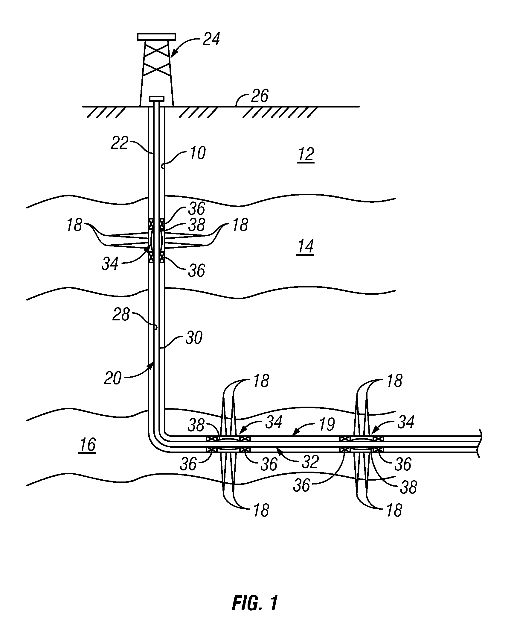
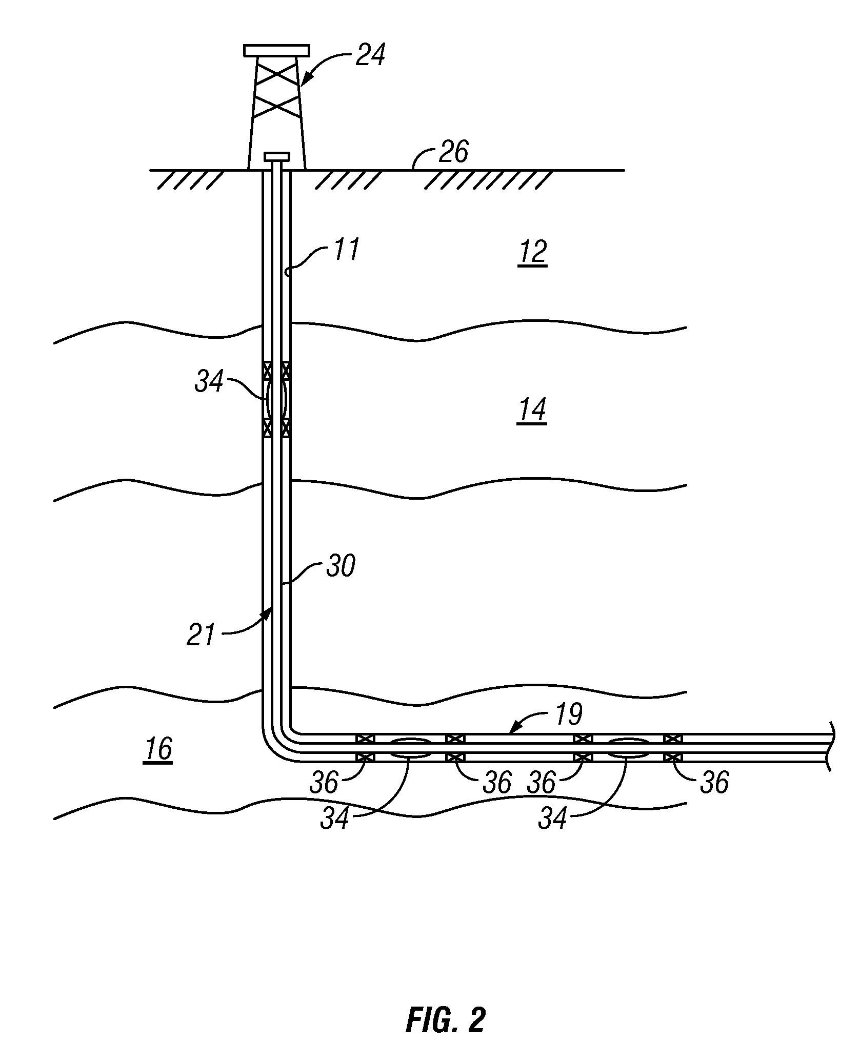
[0019]The present disclosure relates to devices and methods for controlling fluid production at a hydrocarbon producing well. The present disclosure is susceptible to embodiments of different forms. There are shown in the drawings, and herein will be described in detail, specific embodiments of the present disclosure with the understanding that the present disclosure is to be considered an exemplification of the principles of the disclosure, and is not intended to limit the disclosure to that illustrated and described herein.

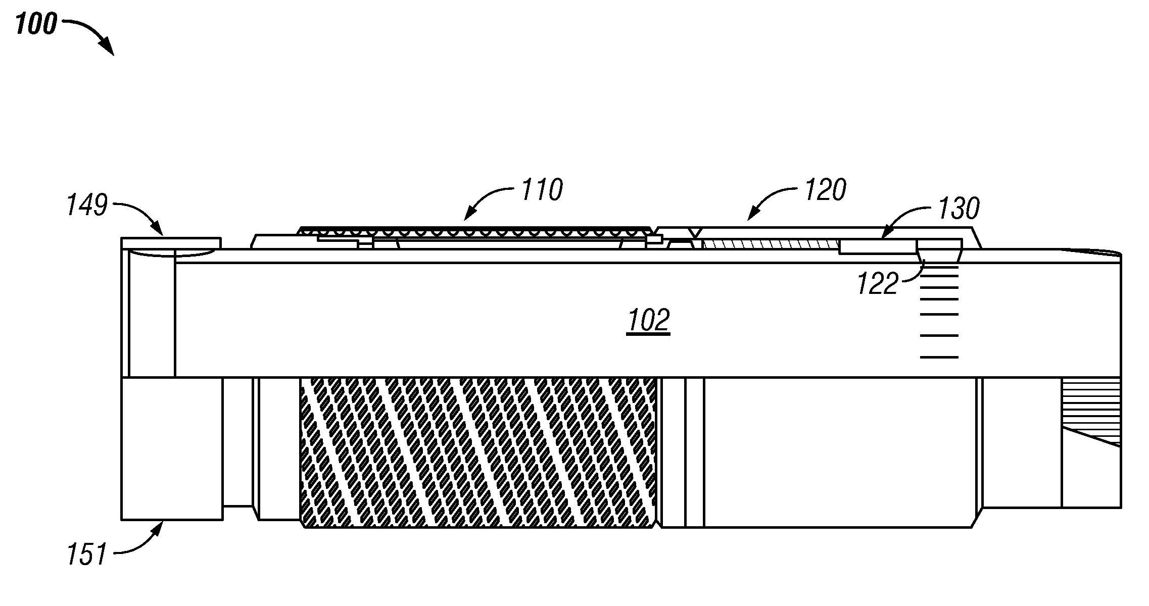
[0020]In embodiments, the flow of formation fluids into the wellbore tubular of an oil well may be controlled, at least in part, by using an in-flow control device that contains a media that may interact with one or more specified fluids produced from an underground formation. The interaction may be calibrated or engineered such that a flow parameter (e.g., flow rate) of the in-flowing formation fluid varies according to a predetermined relationship to a selecte...


PUM


Abstract

An apparatus for controlling fluid flow into a tubular includes an in-flow control device having a plurality of flow paths; and a reactive media disposed in each of the flow paths. The reactive media may change permeability by interacting with a selected fluid such as water. Two or more of the flow paths may be hydraulically parallel. The reactive media may include a Relative Permeability Modifier. An associated method may include conveying the fluid via a plurality of flow paths; and controlling a resistance to flow in plurality of flow paths using a reactive media disposed in each of the flow paths. An associated system may include a wellbore tubular; an in-flow control device; a hydraulic circuit formed in the in-flow control device; and a reactive media disposed in the hydraulic circuit, the reactive media may change permeability by interacting with a selected fluid.

Description

CROSS-REFERENCE TO RELATED APPLICATIONS[0001]This application is a continuation-in-part from U.S. patent application Ser. No. 11 / 871,685 filed Oct. 12, 2007 and also a continuation-in-part of U.S. patent application Ser. No. 11 / 875,669 filed Oct. 19, 2007.BACKGROUND OF THE DISCLOSURE[0002]1. Field of the Disclosure[0003]The disclosure relates generally to systems and methods for selective or adaptive control of fluid flow into a production string in a wellbore.[0004]2. Description of the Related Art[0005]Hydrocarbons such as oil and gas are recovered from a subterranean formation using a wellbore drilled into the formation. Such wells are typically completed by placing a casing along the wellbore length and perforating the casing adjacent each such production zone to extract the formation fluids (such as hydrocarbons) into the wellbore. These production zones are sometimes separated from each other by installing a packer between the production zones. Fluid from each production zone ...

Claims


Application Information

Patent Timeline
Patent Type & Authority Applications(United States)
IPC IPC(8): E21B34/06
CPCE21B34/08E21B43/12
Inventor HUANG, TIANPINGCREWS, JAMESHAMMER, AARON C.CORONADO, MARTIN
Owner BAKER HUGHES INC
Why Eureka
Try Eureka