
Feeding structure for sliding structural body

a technology for sliding structural bodies and feeding structures, which is applied in the direction of cage suspension devices, furniture parts, machine supports, etc., can solve the problems of difficult to absorb a redundant length of wire harnesses, restrict the degree of freedom of arranging other auxiliary devices, and take a lot of labor, so as to reduce the occupied space, thin structure, and compact feeding structure

Active Publication Date: 2009-04-16
YAZAKI CORP +1
View PDF4 Cites 23 Cited by
  • Summary
  • Abstract
  • Description
  • Claims
  • Application Information

AI Technical Summary

Benefits of technology

[0020]In view of the above points, an object of the present invention is to provide a feeding structure for a sliding structural body capable of solving problems of increase in size of a protector and a wire harness so that an installation space can be saved and also capable of decreasing bending stress given to a wire harness so that the durability can be enhanced.
[0027]Due to the above constitution, the torsion coil spring pushes the link arm in a direction so that a redundant length of the wire harness can be absorbed and hanging of the wire harness is prevented when the sliding structural body is opened half. One end of the torsion coil spring is engaged with (supported by) the link arm and the other end of the torsion coil spring is engaged (supported by) with the protector base. When a substantially S-shaped bent portion of the wire harness located along the protector base pushes the harness holder in a direction of absorbing a redundant length of the wire harness at the time of compression, a pushing force of the link arm generated by the elastic member is assisted when the sliding structural body is opened half. Therefore, the redundant length of the harness can be smoothly absorbed.
[0028]According to the above configurations, when the wire harness is laid along the protector base being formed into a substantial S-shape, a space on the surface side of the protector base is effectively put into practical use. Therefore, the feeding structure can be made compact. Since the wire harness is extended and contracted into a substantial S-shape, a redundant length of the wire harness is smoothly absorbed when the sliding structural body is opened half. Since the wire harness is smoothly bent into a substantial S-shape, stress concentration in the wire harness, which is caused in the conventional structure, can be evaded, so that the bending durability of the wire harness can be enhanced. Since the substantially S-shaped bent wire harness pushes the harness holder by a repulsion force in a direction so that a redundant length of the wire harness can be absorbed when the sliding structural body is opened half, the performance of absorbing the redundant length of the wire harness is enhanced. The wire harness is laid in the stationary structural body at the shortest distance from the harness holder. Therefore, the weight of the wire harness can be decreased and the manufacturing cost can be reduced.
[0030]According to the above configurations, when the torsion coil spring is used, as compared with the conventional leaf spring, the occupied space can be reduced and further the structure can be made thin. Therefore, the feeding structure of can be made compact. Further, the substantial S-shaped bent wire harness pushes the harness holder by a repulsion force in a direction so that a redundant length of the wire harness can be absorbed when the sliding structure is opened half. Accordingly, the performance of absorbing the redundant length of the wire harness by the elastic member can be more enhanced.

Problems solved by technology

However, in the first feeding structure of the related art shown in FIG. 4, the following problems may be encountered.
Therefore, the degree of freedom of arranging the other auxiliary devices may be restricted and alternatively, it may become difficult to absorb a redundant length of the wire harness in case that the priority of using the space is given to the arrangement of the other auxiliary devices.
Accordingly, in order to insert the electric wire into the corrugated tube, it takes much labor.
Further, the manufacturing cost is raised and the weight is increased.
The above problems are caused in the same manner not only in the case where the feeding unit is applied to the slide door of an automobile but also in the case where the feeding unit is applied to the sliding structural body such as a slide door of a train or a slide door of a manufacturing apparatus or a detection apparatus.

Method used


Image

  • Feeding structure for sliding structural body
  • Feeding structure for sliding structural body
  • Feeding structure for sliding structural body

Examples


Embodiment Construction

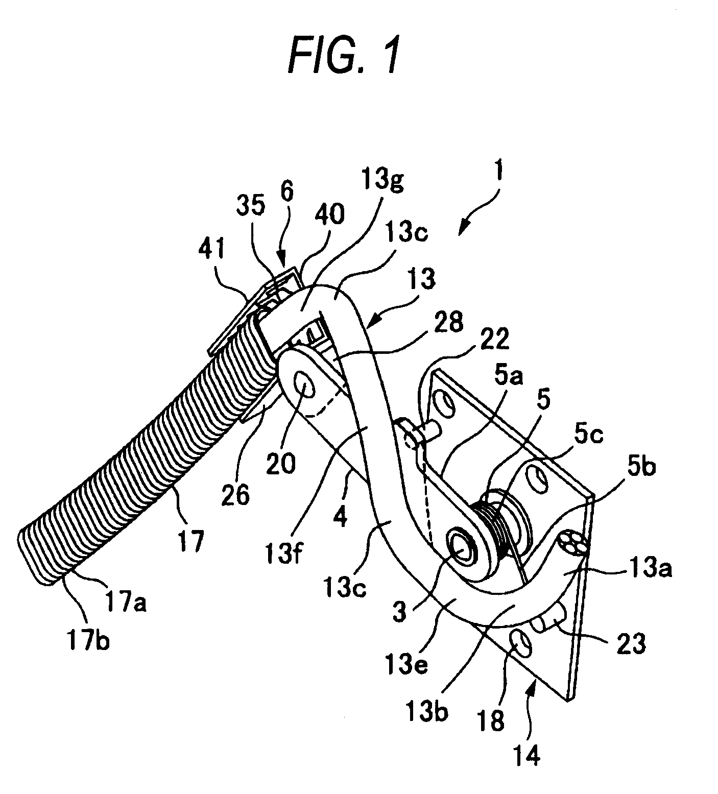
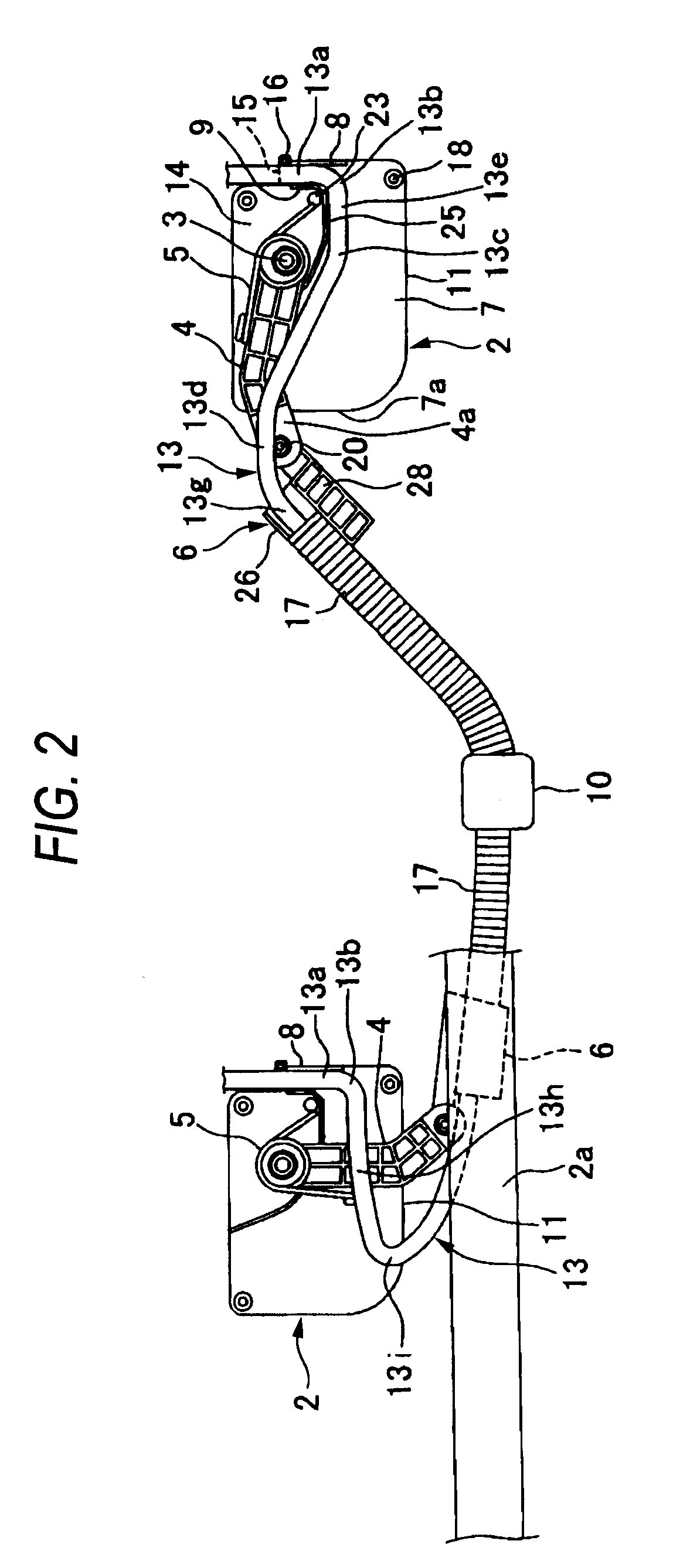
[0039]FIGS. 1 to 3 are views showing an embodiment of the feeding structure for a sliding structural body of the present invention. In FIG. 2, for the convenience of explanations, operation states of the feeding unit at the time of opening and closing the sliding structural body are respectively shown by solid lines.

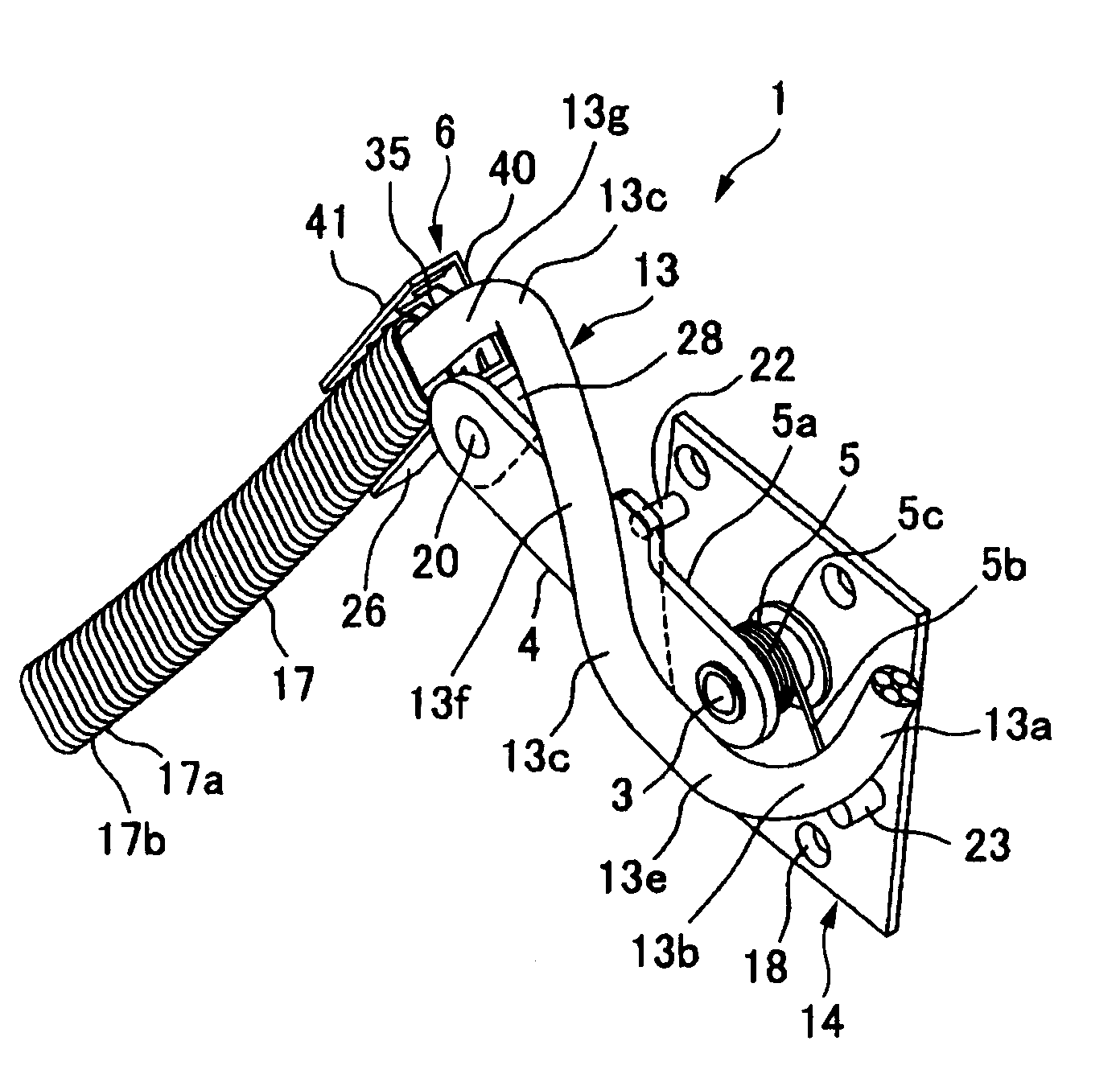
[0040]As shown in FIG. 1, this feeding structure includes: a protector base 2 (shown in FIG. 2) made of synthetic resin vertically (longitudinally) mounted on a slide door (a sliding structural body) of an automobile; one link arm 4 made of synthetic resin, the shaft portion 3 on the base portion side of the link arm being pivotally supported by the protector base 2; a torsion coil spring (an elastic member) 5 made of metal for pushing the link arm 4 upward; a harness holder 6 made of synthetic resin pivotally connected to a forward end portion of the link arm 4; and a wire harness 13 which is laid from the forward end side of the protector base 2 to the harness holder 6...


PUM


Abstract

A feeding structure for a sliding structural body includes: a protector base arranged in one of the sliding structural body and a stationary structural body; a link arm pivotally supported by a shaft portion of the protector base; a harness holder pivotally connected to an end portion of the link arm; and a wire harness which is laid from one end of the protector base to the harness holder so as to be bent in a substantial S-shape, and laid from the harness holder to the other of the sliding structural body and the stationary structural body so as to be moved therebetween.

Description

BACKGROUND OF THE INVENTION[0001]1. Technical Field[0002]The present invention relates to a feeding structure for a sliding structural body in which a redundant length of a wire harness is absorbed by a link arm pivotally arranged on a protector base.[0003]2. Background Art[0004]FIG. 4 is a view showing a first configuration of the conventional feeding structure for a sliding structural body. Concerning this matter, refer to Patent Document 1.[0005]This feeding structure adopts a feeding unit 51. The feeding unit 51 includes: a guide rail 53 horizontally arranged in the slide door 52 of an automobile; a slider 54 slidably engaged with the guide rail 53; and a pair of V-shaped links 55, 56, which can be freely opened and closed, and one end portion of the link 55 is connected to the slider 54 and the one end of the link 56 is connected to the guide rail 53.[0006]The wire harness 57 is laid from the link 55 to the stationary portion 59 on the vehicle body side 58 through the slider 54...

Claims


Application Information

Patent Timeline
IPC IPC(8): A47B96/06
CPCB60R16/0215
Inventor KATOU, MITSUNOBUAOKI, TOHRU
Owner YAZAKI CORP
Learn More