Rotor For Electric Motor

a technology of electric motors and rotors, applied in the direction of electrical apparatus, magnetic circuits, dynamo-electric machines, etc., can solve the problems of potential reduction of motor efficiency, potential field loss, and full utilization of magnets, and achieve the effect of reducing manufacturing costs and increasing efficiency

Inactive Publication Date: 2009-04-16
THYSSENKRUPP PRESTA AG
View PDF7 Cites 88 Cited by
  • Summary
  • Abstract
  • Description
  • Claims
  • Application Information

AI Technical Summary

Benefits of technology

[0009]The present invention addresses the problem of eliminating at least some of the disadvantages of prior art. In particular, a compact electric motor with increased efficiency at lower manufacturing cost i...

Problems solved by technology

In addition, in such applications often as compact a structuring method as possible is required.
Disadvantages of known motor configurations are that the disposition of the permanent magnets, together with the laminated core arrangements, for the guidance of the magnetic fluxes for the development of ...

Method used


Image

  • Rotor For Electric Motor
  • Rotor For Electric Motor
  • Rotor For Electric Motor

Examples


Embodiment Construction

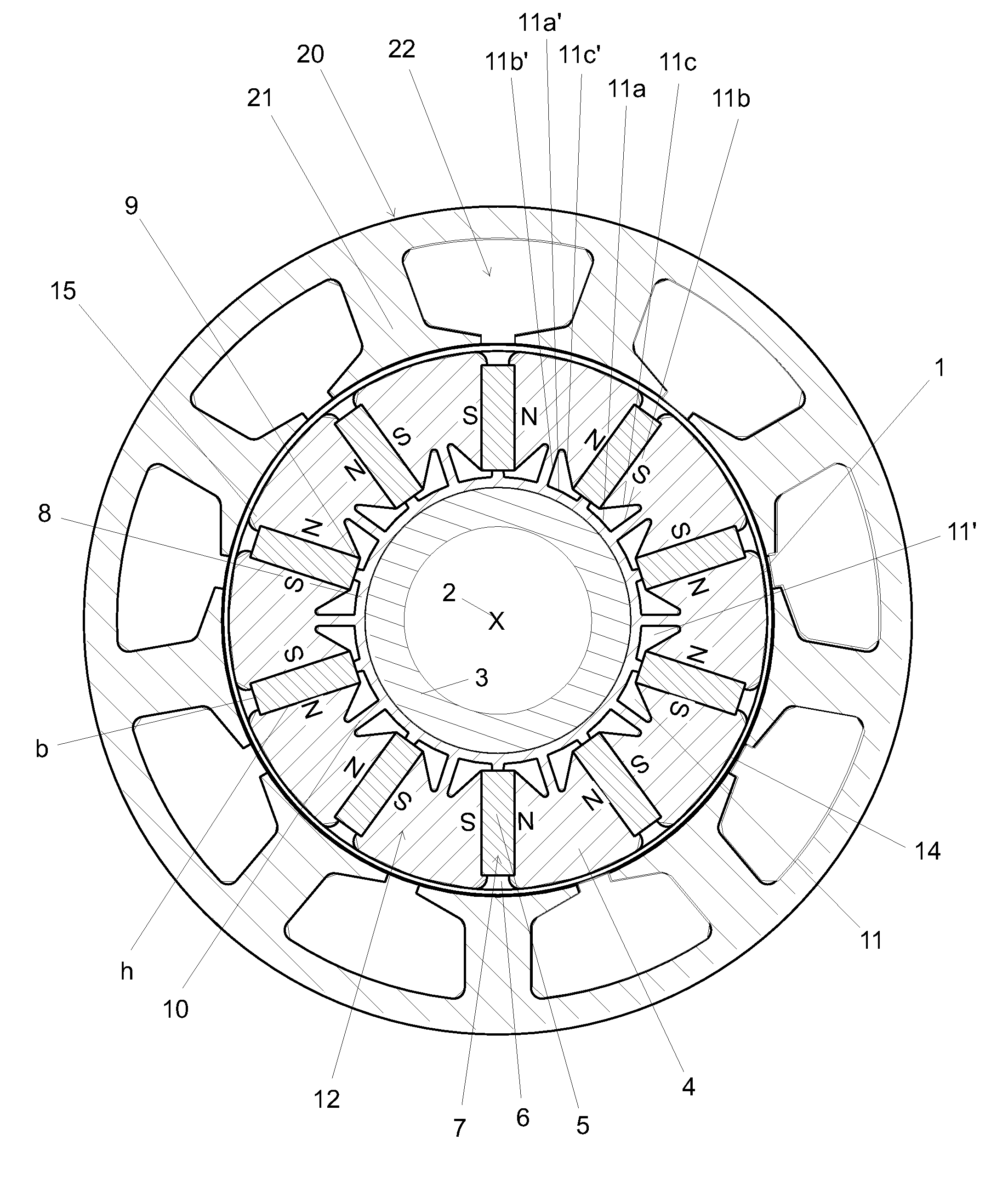
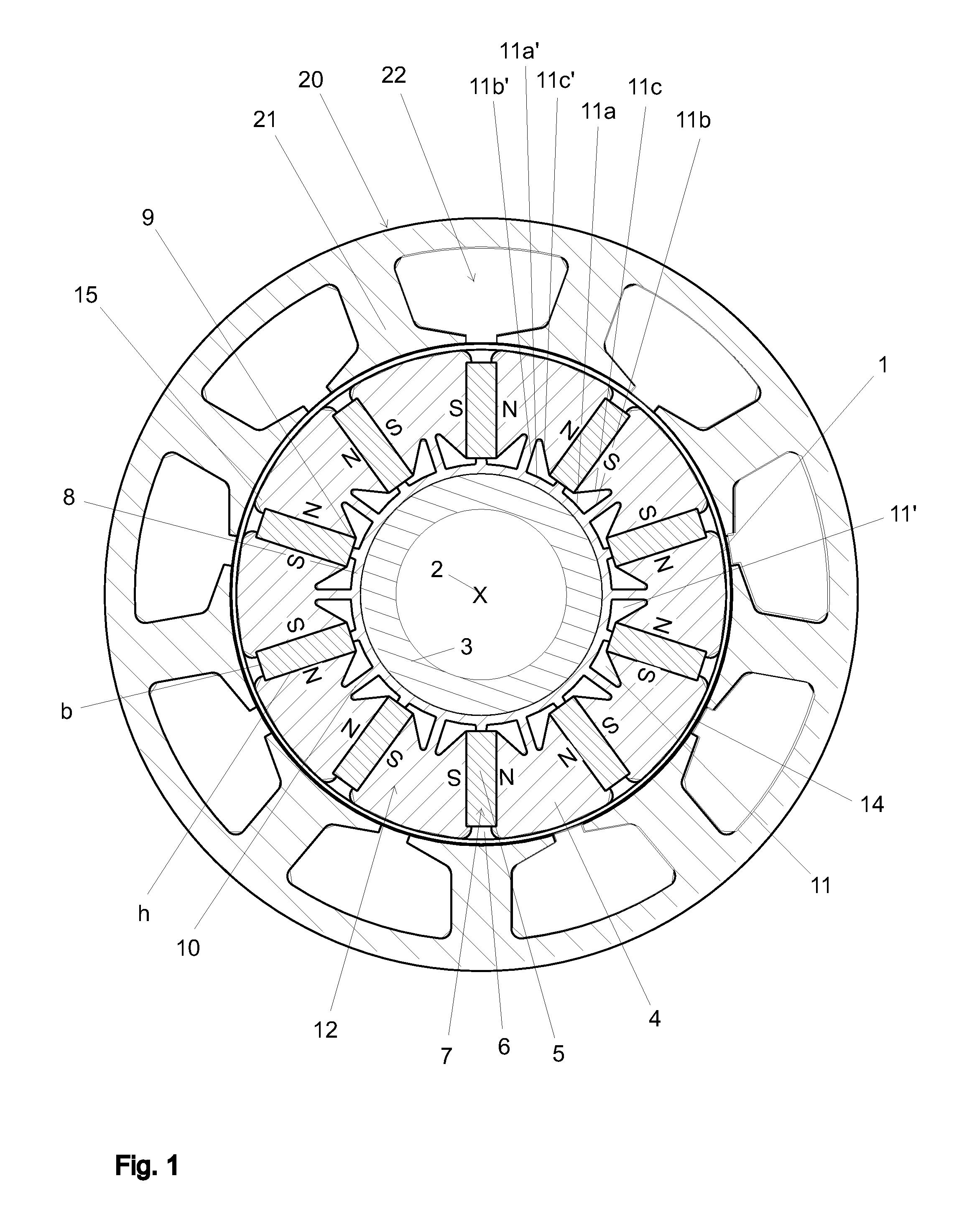
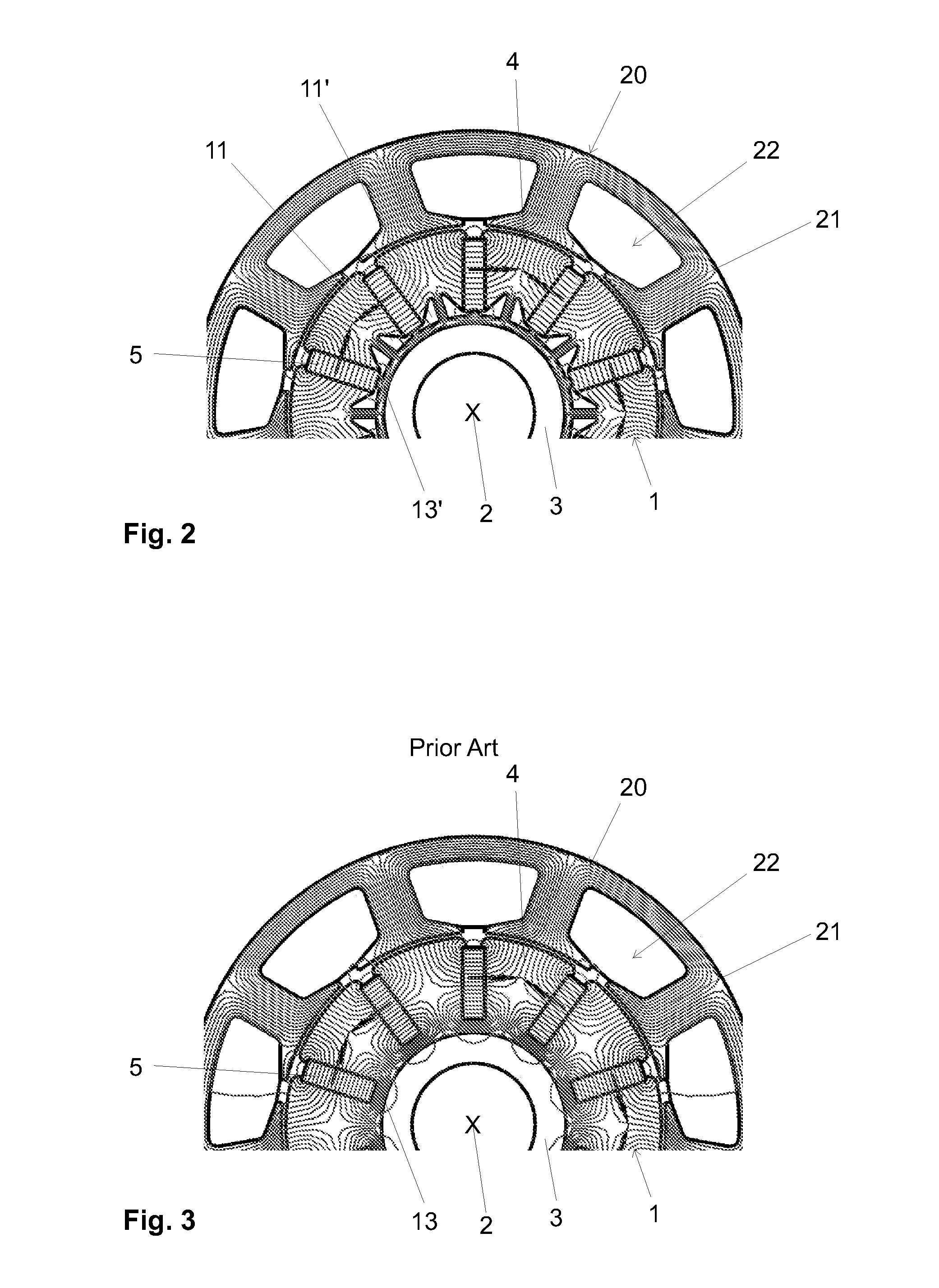
[0054]An electric motor according to the invention with magnetic flux under optimized guidance in the rotor is depicted in cross section in FIGS. 1, 2, 12 and 13. The electric motor contains a rotor 1, which is supported rotatably about the central motor axis 2 with a motor shaft 3 and a stator 20 encompassing the rotor 1. The stator 20 includes stator poles 21 of a magnetic material, which are directed toward the rotor 1, which comprises rotor poles 4 of a magnetic material and is spaced apart from it across a small air gap 14, such that the rotor 1 is not in contact with the stator 20 and can freely rotate. Each of the stator poles 21 carries a stator winding 22 for generating a rotary field This rotary field is preferably generated with electronic means and can, according to the desired operating conditions, be controlled and regulated in different ways, such as for example frequency and power.

[0055]The rotor poles 4 of magnetic material are disposed in a rotor ring 12 about the ...


PUM

PropertyMeasurementUnit
Fractionaaaaaaaaaa
Fractionaaaaaaaaaa
Fractionaaaaaaaaaa

Abstract

An electric motor has an internal ferromagnetic rotor ring and an external stator. Circumferentially distributed cutouts in the rotor receive rectangular permanent magnets each having a width b and height h and the rotor ring is divided into rotor poles. The height h forms the longer side of each magnet and is radial to the motor axis. The magnets are magnetized in the width b direction with like poles oriented toward one another. A magnetic clearance is located between adjacent magnets for each inner portion of a rotor pole. The clearance does not contain magnetic material and in a center region of the rotor poles one support web connects an inner support ring with the particular rotor pole to provide mechanical support.

Description

FIELD AND BACKGROUND OF THE INVENTION[0001]The invention relates to an electric motor and to a method for the production of an electric motor.[0002]Such electric motors are employed wherever high power performance with electronically controllable rotational number is required and with a response behavior with as short a delay as possible. In addition, in such applications often as compact a structuring method as possible is required. In the case of electric motors of this type the magnetic field of the rotor is generated with high-power permanent magnets and the rotating field is generated with externally located stator windings encompassing the rotor, which windings are electronically energized or commutated or regulated. The regulation preferably takes place as a sinusoidal regulation (FOC). The permanent magnets are conventionally slid into a rotor ring of magnetic material and fastened, which ring is comprised of a full laminated core and encompasses the magnets as is shown sche...

Claims


Application Information

Patent Timeline
IPC IPC(8): H02K21/12H02K15/03
CPCY10T29/49012H02K1/2773
Inventor STAUDENMANN, CHRISTIAN
Owner THYSSENKRUPP PRESTA AG
Why Eureka
Try Eureka