Stator for rotating electrical machine, part to be used for stator and method for manufacturing stator for rotating electrical machine

a technology for rotating electrical machines and stators, which is applied in the direction of prefabricated windings, dynamo-electric components, windings, etc., can solve the problems of resin protruding from the cover, the gap cannot be filled, and the insulating performance cannot be guaranteed. , to achieve the effect of suppressing deterioration of workability, suppressing deterioration of insulating performance, and improving space factor

Inactive Publication Date: 2009-04-16
TOYOTA JIDOSHA KK
View PDF10 Cites 50 Cited by
  • Summary
  • Abstract
  • Description
  • Claims
  • Application Information

AI Technical Summary

Benefits of technology

[0010]An object of the present invention is to provide a stator for a rotating electrical machine capable of achieving both improvement of a space factor and insulation between coil turns, a part to be used for the stator, and a method for manufacturing the stator. Another object of the present invention is to provide a stator for a rotating electrical machine capable of suppressing deterioration of workability, and a method for manufacturing the stator. Still another object of the present invention is to provide a stator for a rotating electrical machine capable of suppressing deterioration of insulating performance due to heat generated in a joining process, and a method for manufacturing the stator.

Problems solved by technology

In the stator for the rotating electrical machine disclosed in the foregoing publication, however, if the space factor is further enhanced, there arises a problem that the insulating performance can not be ensured sufficiently.
Consequently, if the gap is further decreased for enhancing the space factor, there is a possibility that the gap can not be filled with the resin having a certain viscosity.
However, as the gap becomes smaller, a possibility that the resin protrudes from the cover becomes higher.
Consequently, there arises a problem that workability deteriorates.
There is no inexpensive organic material which can be molded and is not melted even at a high temperature; consequently, a problem that insulating performance becomes deteriorated is inevitable.
Moreover, if a joining material which is low in heating temperature (about 350° C.) in a joining process such as soldering is used for preventing the insulating member from being melted, there is a possibility that the heat (about 200° C.) generated upon actuation of the rotating electrical machine deteriorates a joining strength of the joining material.
Consequently, there is a possibility that the insulation is damaged due to burrs or powders resulting from the cutting process.

Method used


Image

  • Stator for rotating electrical machine, part to be used for stator and method for manufacturing stator for rotating electrical machine
  • Stator for rotating electrical machine, part to be used for stator and method for manufacturing stator for rotating electrical machine
  • Stator for rotating electrical machine, part to be used for stator and method for manufacturing stator for rotating electrical machine

Examples


Embodiment Construction

[0054]Hereinafter, an embodiment of the present invention is described with reference to the drawings. In the following description, identical parts are denoted by identical reference symbols. Designations and functions thereof are the same. Accordingly, detailed description thereof is not repeated.

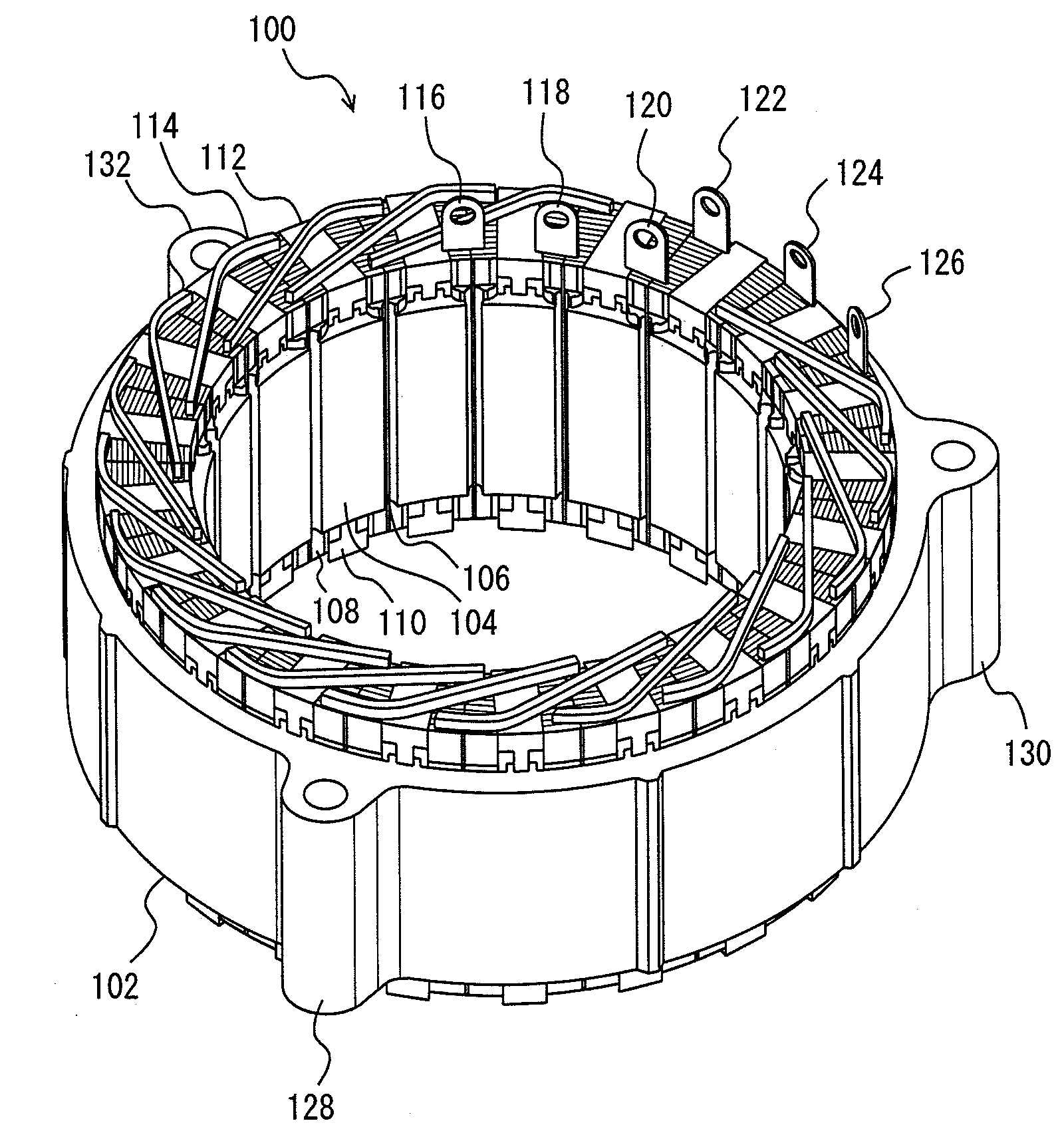
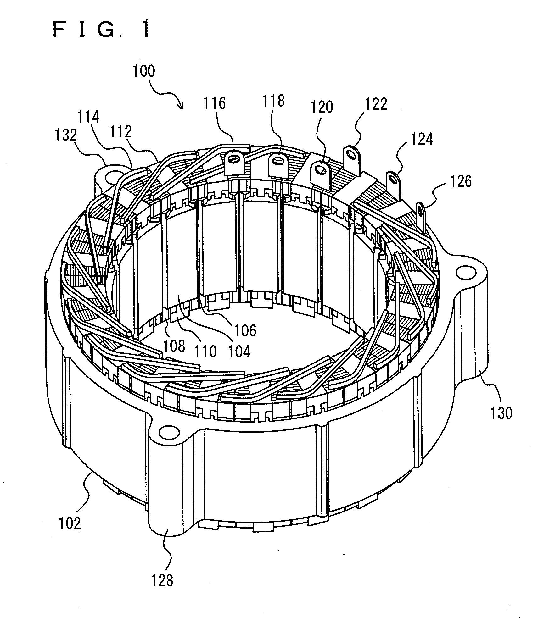
[0055]A stator according to the present embodiment is a stator for a rotating electrical machine constituted of the stator and a rotor including a permanent magnet. In the present embodiment, the stator is a stator for a three-phase AC synchronization rotating electrical machine of which the number of poles is 21. However, the present invention should be applied to a stator around which a coil is wound, and the number of poles is not particularly limited to 21. Further, it should not be understood that the present invention is applied to only the stator for the three-phase AC synchronization rotating electrical machine.

[0056]As shown in FIG. 1, a stator 100 is constituted of a stator core...


PUM

PropertyMeasurementUnit
temperatureaaaaaaaaaa
eutectic temperatureaaaaaaaaaa
melting temperatureaaaaaaaaaa

Abstract

A stator includes a stator core having a plurality of slots in a direction parallel to the rotating shaft of a rotating electrical machine; and a coil plate laminated body formed by laminating a plurality of I-shaped coil plates, each of which has an insulating film adhered at least on one side, in a diameter direction. In the coil plate laminated body, a plurality of coil plates are inserted inside a resin insulator inserted into the slots so that the insulating film is arranged between the coil plates, and the coil plates are integrally held by the resin insulator. The resin insulator integrally holds the coil plate laminated body of a plurality of phases in the same slot.

Description

TECHNICAL FIELD[0001]The present invention relates to a stator for a rotating electrical machine, a part to be used for the stator, and a method for manufacturing the stator for the rotating electrical machine. In particular, the present invention relates to a stator having a structure for improving insulating performance and productivity, a part to be used for the stator, and a method for manufacturing the stator.BACKGROUND ART[0002]As a stator for a rotating electrical machine including the stator and a rotor, conventionally, there has been disclosed a stator formed in such a manner that an integral laminated coil is inserted into a slot between a plurality of teeth provided in a stator core. In the integral laminated coil, for example, two sets of coil laminated bodies each having a plurality of linear and thin conductors laminated are integrally formed by resin molding. The thin conductors are laminated so as to be close to a sectional area of the slot in a direction orthogonal ...

Claims


Application Information

Patent Timeline
Patent Type & Authority Applications(United States)
IPC IPC(8): H02K23/26H02K15/06
CPCH02K3/522H02K15/0081Y10T29/49009H02K3/50H02K15/12
Inventor HARADA, KENJITAKETSUNA, YASUJIFUBUKI, SHINGO
Owner TOYOTA JIDOSHA KK
Why Eureka
Try Eureka