Brush Board for High Current Electric Motor

a high-current electric motor and brush board technology, applied in current collectors, dynamo-electric machines, current collectors, etc., can solve the problems of difficult replacement of worn brushes, limited temperature load capacity of each motor, and limited light-duty operation of the motor, so as to achieve simple installation

Inactive Publication Date: 2009-04-16
MANTLE ELTON L
View PDF4 Cites 12 Cited by
  • Summary
  • Abstract
  • Description
  • Claims
  • Application Information

AI Technical Summary

Benefits of technology

[0005]Accordingly, it is an object of this invention to provide a brush board assembly for use in an electric motor, which is strong and durable, simple to install, and which avoids the drawbacks of the prior art.

Problems solved by technology

These all employ a single support plate with a number of brush holders mounted or formed on it, and each has a limited ability to withstand temperature loads.
This construction can limit the motor to lighter duty operation.
Also, in the motors of the prior art it has been difficult to replace worn brushes, and it is usually necessary to disassemble the brush board to achieve that, if it is even possible to do so.
There can be a substantial voltage drop through the brushes and commutator, producing significant heating of the brush holder arrangement during normal operation.

Method used


Image

  • Brush Board for High Current Electric Motor
  • Brush Board for High Current Electric Motor
  • Brush Board for High Current Electric Motor

Examples


Embodiment Construction

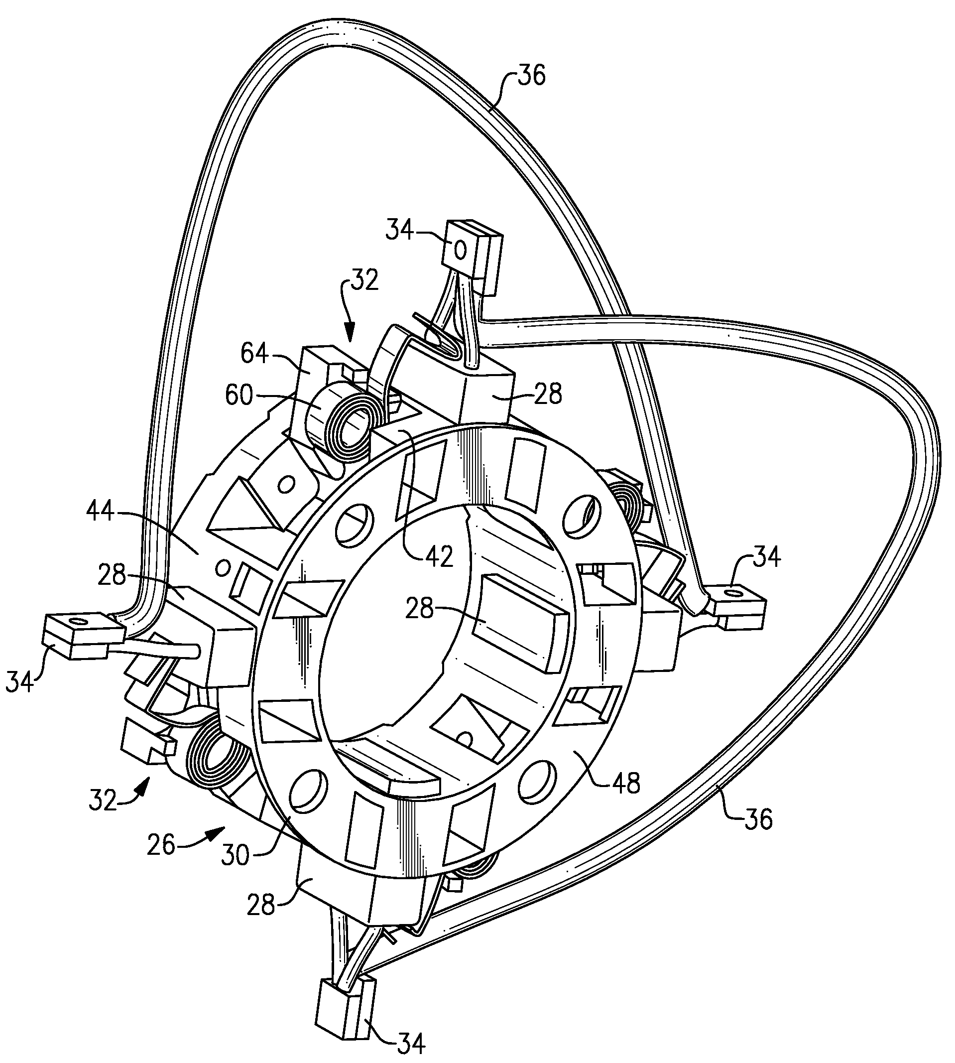
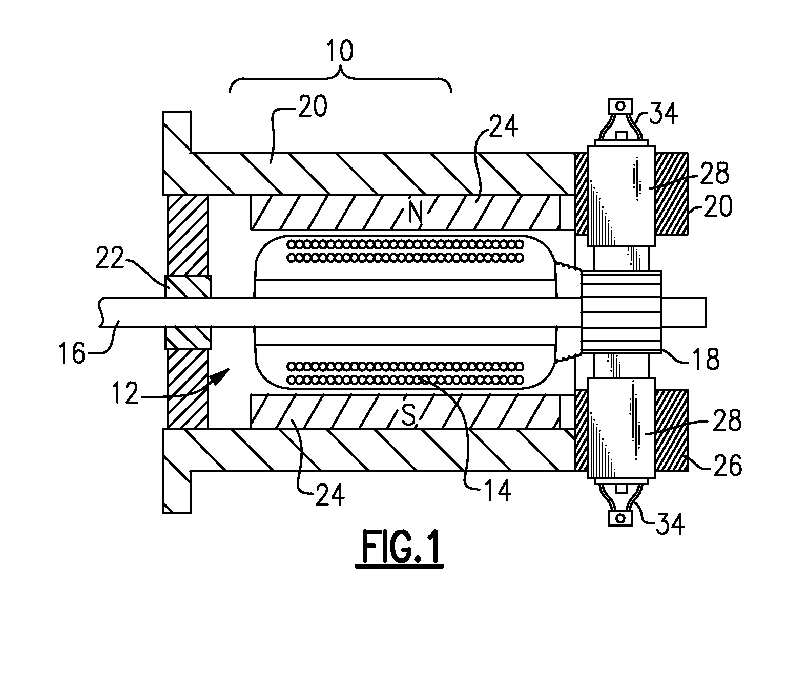
[0021]Now with reference to the Drawing, FIG. 1 shows schematically a DC motor 10 incorporating the brush board arrangement according one embodiment of the invention. Here the arrangement motor 10 is shown with a rotor 12 having a rotary armature 14 that consists of a number of windings upon a rotor shaft 16. A commutator 18 is disposed at one end of the shaft. Here, the commutator is in the form of a series of contact bars arranged cylindrically about the shaft. The principles of this invention could also be applied to motors of the type having a commutator arrangement formed of number of slip rings, e.g., an AC motor. The rotor is housed in a case or housing 20, with a bearing 22 at one end supporting the shaft 16. Here the stator or field magnet element of the motor is formed by a plurality of permanent magnets 24, 24 mounted onto an interior wall of the housing 20.

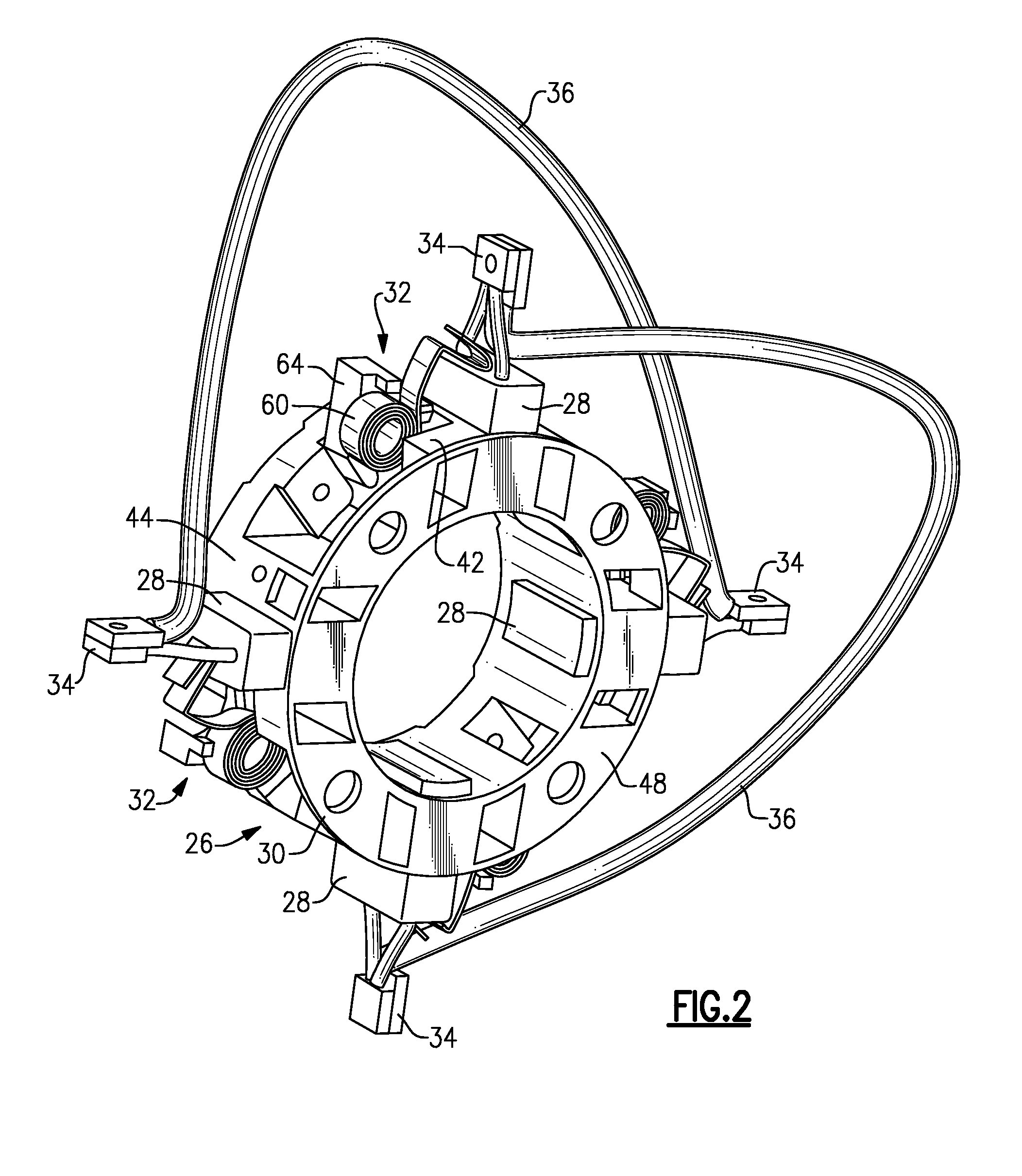
[0022]A brush board and brush holder assembly 26, of the type that embodies the present invention, is mounted on the...


PUM


Abstract

A brush board assembly for a DC or AC motor employs a spool-shaped frame unitarily formed of a mounting plate, a series of support members that extend axially and define the brush holders, and an outer support plate that is generally parallel to the mounting plate. This frame may be molded of a high strength, high temperature resin for heavy duty motor use. Brush hold down springs are mounted onto push-in carriers that fit into receptacles on the support members. Preferably, scroll or volute springs are employed, and a stop arm on the carrier allows the free end of the spring to be held out of the way for installation or brush change out.

Description

BACKGROUND OF THE INVENTION[0001]This invention is directed to electromagnetic rotating machines, and is more particularly directed to an assembly for holding brushes in position in an electrodynamic motor. The invention is more particularly concerned with a brush board and brush holder assembly that may be molded of a high performance plastic resin, with the brush board frame and brush holders unitarily formed for increased strength and durability under heavy duty operating conditions.[0002]In DC motors of the type in which a rotary armature is supplied current through a rotary commutator, it is typical to mount the brushes in brush holders or brush boxes that are attached to a frame or support plate, i.e., a brush board, which is mounted to one end of the motor housing. This will typically have a center aperture to accommodate the commutator structure. The brush boxes or brush holders are separate items, usually made of steel or brass, and are mounted to the brush board by means o...

Claims


Application Information

Patent Timeline
Patent Type & Authority Applications(United States)
IPC IPC(8): H02K5/14H01R39/02H01R39/38H01R39/40
CPCH01R39/381H02K5/148H01R39/40
Inventor MANTLE, ELTON L.
Owner MANTLE ELTON L
Why Eureka
Try Eureka