
Methods and Systems for Measurement of Fluid Electrical Stability

a technology of electrical stability and measurement method, applied in the direction of fluid resistance measurement, material breakdown voltage, instruments, etc., can solve the problems of significant negative consequences of drilling operations, increased cost of remedial action, and solids in drilling fluid to become water w

Active Publication Date: 2009-04-16
HALLIBURTON ENERGY SERVICES INC
View PDF6 Cites 14 Cited by
  • Summary
  • Abstract
  • Description
  • Claims
  • Application Information

AI Technical Summary

Benefits of technology

[0001]The present invention relates to methods and apparatuses for characterizing or evaluating the strength or effectiveness of oil-based drilling fluids for use in drilling well bores in subterranean form

Problems solved by technology

If the formulation of the invert emulsion drilling fluid becomes unbalanced, due to, for example (without limitation), contamination, improper product additions, or thermal degradation, the oil-based drilling fluids tend to revert to an oil-in-water emulsion.
As a result of the reversion to an oil-in-water emulsion, the water becomes the continuous phase and can cause the solids in the drilling fluid to become water wet.
Such wetting has significant negative consequences to a drilling operation and requires expensive remedial action in order to prevent the loss of the well.
However, the typical method of use of an EST, as discussed above, has many drawbacks.
One disadvantage of the current method is that the oil-based drilling fluid sample must be screened with a Marsh funnel and heated or cooled to the test temperature prior to each measurement in order to obtain consistent Electrical Stability values.
This can be time consuming and burdensome.
Yet another problem with the current method is that the contamination on the surface of the molded insulation of the EST probe can create a conductive path around the electrode gap allowing the current flow between the electrodes to bypass the sample in the gap.
The above pitfalls associated with the current method of measuring Electrical Stability make this method time consuming and prone to errors.
The problem is further compounded by the fact that typically a Mud Engineer must manually obtain frequent Electrical Stability measurements during the drilling operations thereby making the current methods also labor intensive and expensive.

Method used


Image

  • Methods and Systems for Measurement of Fluid Electrical Stability
  • Methods and Systems for Measurement of Fluid Electrical Stability
  • Methods and Systems for Measurement of Fluid Electrical Stability

Examples


Embodiment Construction

[0020]The present invention relates to methods and apparatuses for characterizing or evaluating the strength or effectiveness of oil-based drilling fluids for use in drilling well bores in subterranean formations. The invention relates particularly to methods and apparatuses for characterizing water-in-oil or invert emulsion fluids for use in drilling well bores in hydro-carbon bearing subterranean formations.

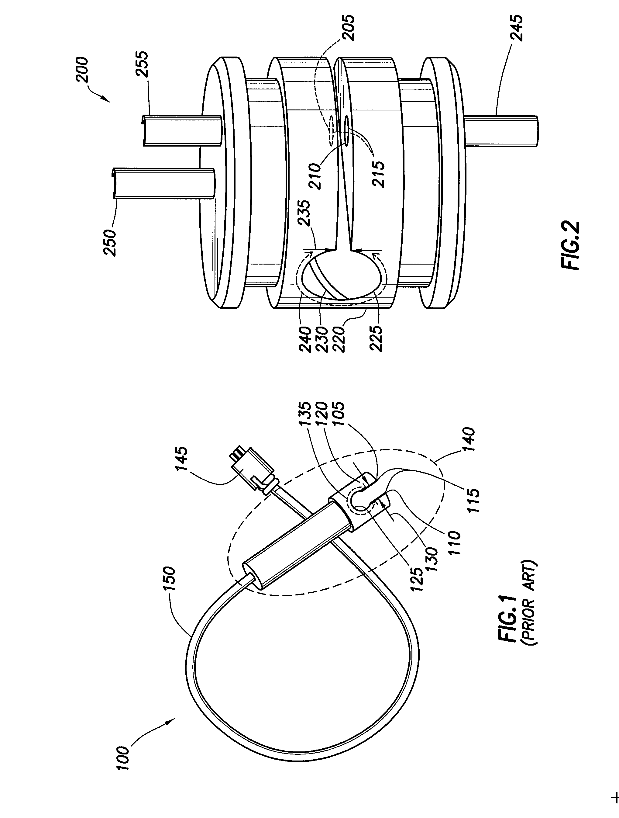
[0021]The details of the present invention will now be discussed with reference to the figures. Turning to FIG. 1, the Probe of an Electric Stability Tester (EST) in accordance with the prior art is shown generally by reference numeral 100. The Probe includes a First Electrode 105 and a Second Electrode 110 collectively referred to as the Measurement Electrodes 115. The Measurement Electrodes 115 are precisely spaced apart and molded into an Electrically Insulating Body 120. The Electrically Insulating Body 120 has a rounded Opening 125 at the end of the Electrode Gap 130 that ...


PUM


Abstract

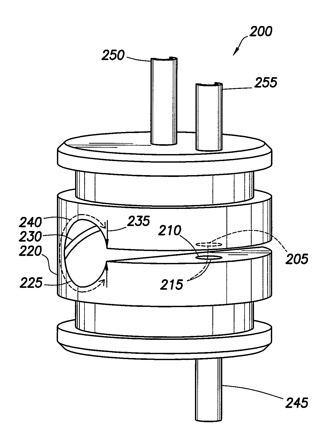
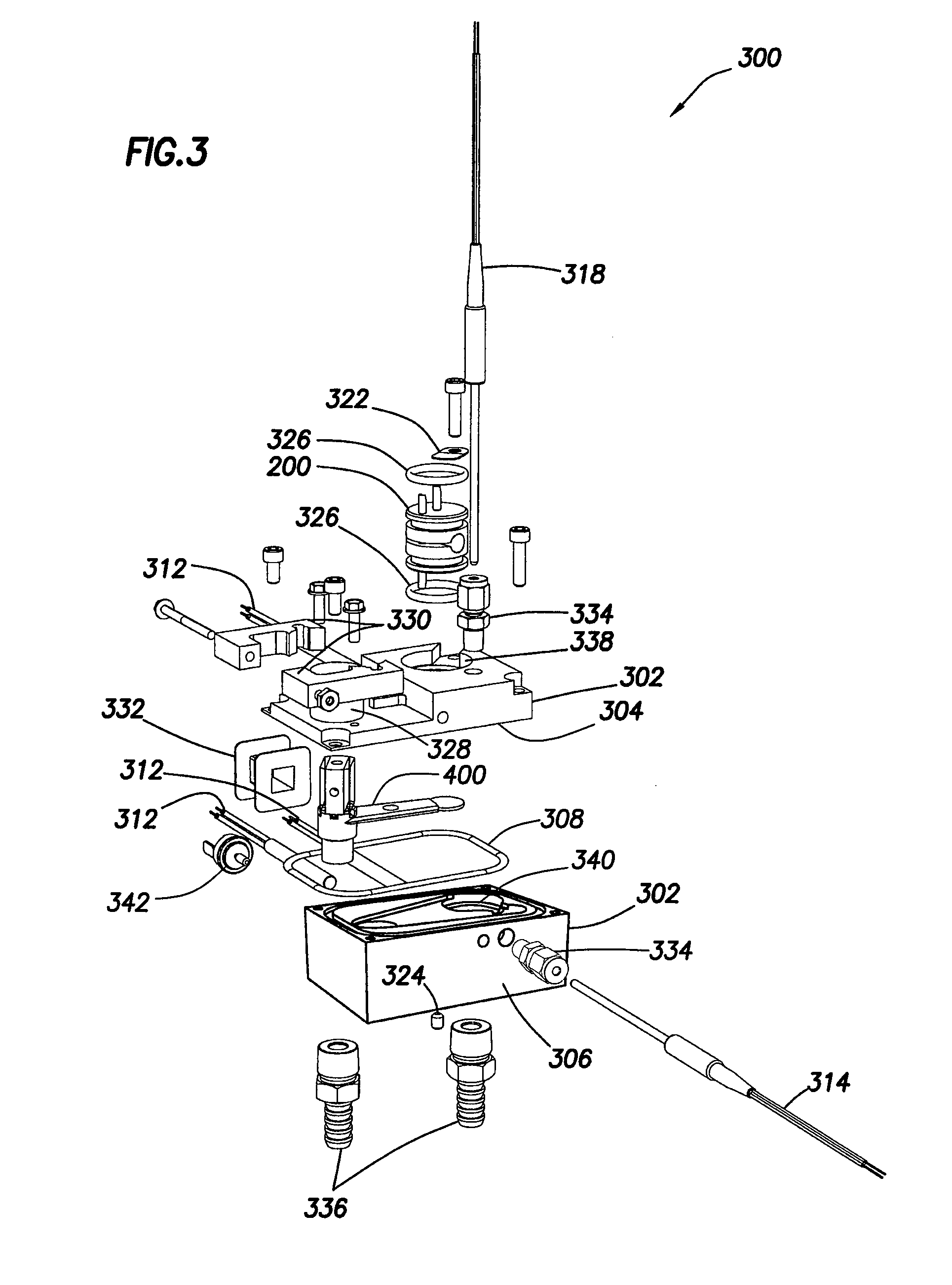
The invention relates particularly to methods and apparatuses for characterizing water-in-oil or invert emulsion fluids for use in drilling well bores in hydro-carbon bearing subterranean formations. A fluid stability measurement device is disclosed. The device comprises a reference electrode and a second electrode coupled to an insulating body. A guard electrode is placed in the path between the reference electrode and the second electrode on the surface of the insulating body.

Description

BACKGROUND OF THE INVENTION[0001]The present invention relates to methods and apparatuses for characterizing or evaluating the strength or effectiveness of oil-based drilling fluids for use in drilling well bores in subterranean formations. The invention relates particularly to methods and apparatuses for characterizing water-in-oil or invert emulsion fluids for use in drilling well bores in hydro-carbon bearing subterranean formations.[0002]Drilling fluids are frequently used in oil and gas drilling operations. These fluids serve many purposes including, but not limited to, removing the cuttings produced, lubricating and cooling the drill bit, and supporting the walls of the hole being drilled.[0003]Oil-based drilling fluids are frequently used when drilling wells for oil and gas. These oil-based drilling fluids are typically water-in-oil emulsions that are stabilized with the addition of emulsifiers. The water phase is usually about 5% to about 40% of the total liquid volume and i...

Claims


Application Information

Patent Timeline
IPC IPC(8): G01R19/165G01K13/00
CPCG01N27/07G01N33/2823G01N27/92
Inventor MURPHY, ROBERTJAMISON, DALE
Owner HALLIBURTON ENERGY SERVICES INC
Learn More