Driver Alert System for the Steering Wheel of a Motor Vehicle

a technology for steering wheels and alert systems, which is applied in the direction of tactile signalling systems, motor/generator/converter stoppers, dynamo-electric converter control, etc. it can solve the problems of increasing costs and slow speed of rotation of motors, so as to improve the alerting effect, increase the effect of invention, and decelerate the motor more quickly

Active Publication Date: 2009-04-16
AUTOLIV DEV AB
View PDF8 Cites 6 Cited by
  • Summary
  • Abstract
  • Description
  • Claims
  • Application Information

AI Technical Summary

Benefits of technology

[0008]The effect of the invention can be increased by preferably setting the over-controlled voltage to be at least 20%, more preferably at least 50% with respect to the normal operation voltage level.
[0009]According to another aspect of the invention which is independent of the aspect mentioned before, the motor is under-controlled with respect to zero level at the end of the vibration period. The following description is based on an under-controlled current but is also valid for an under-controlled voltage. At the end of the vibration period, current control is performed to generate a reverse current with respect to the operation current level during vibration. The under-control generates a torque counteracting the rotation of the motor, and therefore decelerates the motor more quickly in comparison to switching the motor off only. The more or less abrupt halting of the motor contributes to improving the alerting effect.
[0010]As an alternative to actively controlling the motor at the end of the vibration period, a current maintaining path for the motor and circuitry for opening the current maintaining path at the end of the vibration period may be opened. If the motor is switched off at the end of the vibration period, the opening of the current maintaining path allows the motor to function as a generator, whereby the electric energy stored in the electric motor can be passed off quickly through the current maintaining path, which quickly slows down the motor by reducing its rotational energy.
[0011]Preferably the vibration periods are separated by non-vibration periods in order to distinguish the alert vibrations clearly from other vibrations. This is preferably achieved by periodically interrupting the supply of operation voltage, in particular by periodically applying zero voltage to said electric motor,

Problems solved by technology

When the driver alert system of the prior art is activated by supplying a voltage to the electric motor in order to cause vibrations in the steering wheel rim, the rotation frequency of the motor may accelerate only slowly and under negative circumstances may even be trapped at a resonance frequency of the steering wheel column.
This could be overcome by using a stronger electric motor which however would require more space and leads to an increase of costs.

Method used


Image

  • Driver Alert System for the Steering Wheel of a Motor Vehicle
  • Driver Alert System for the Steering Wheel of a Motor Vehicle
  • Driver Alert System for the Steering Wheel of a Motor Vehicle

Examples


Embodiment Construction

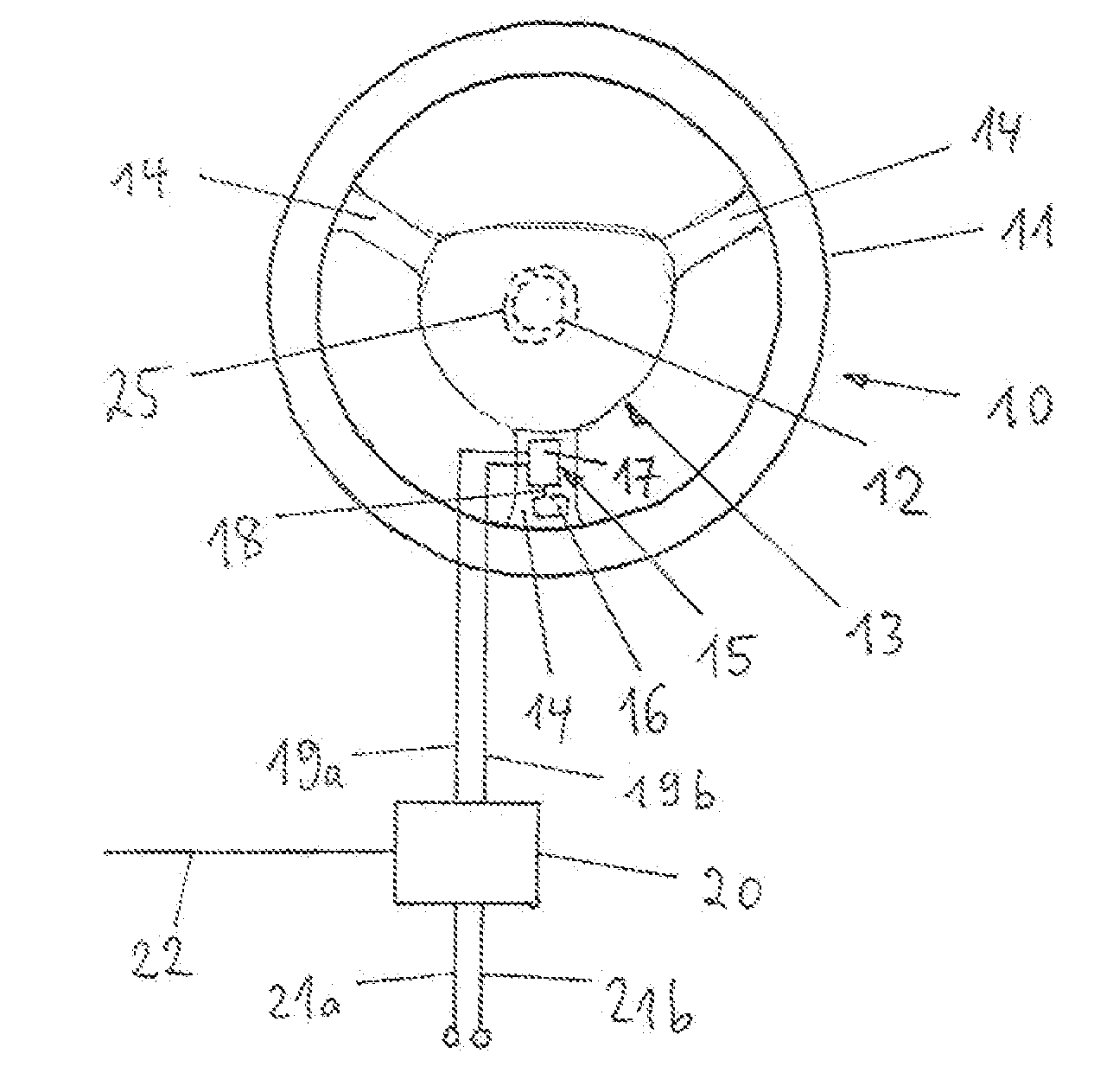
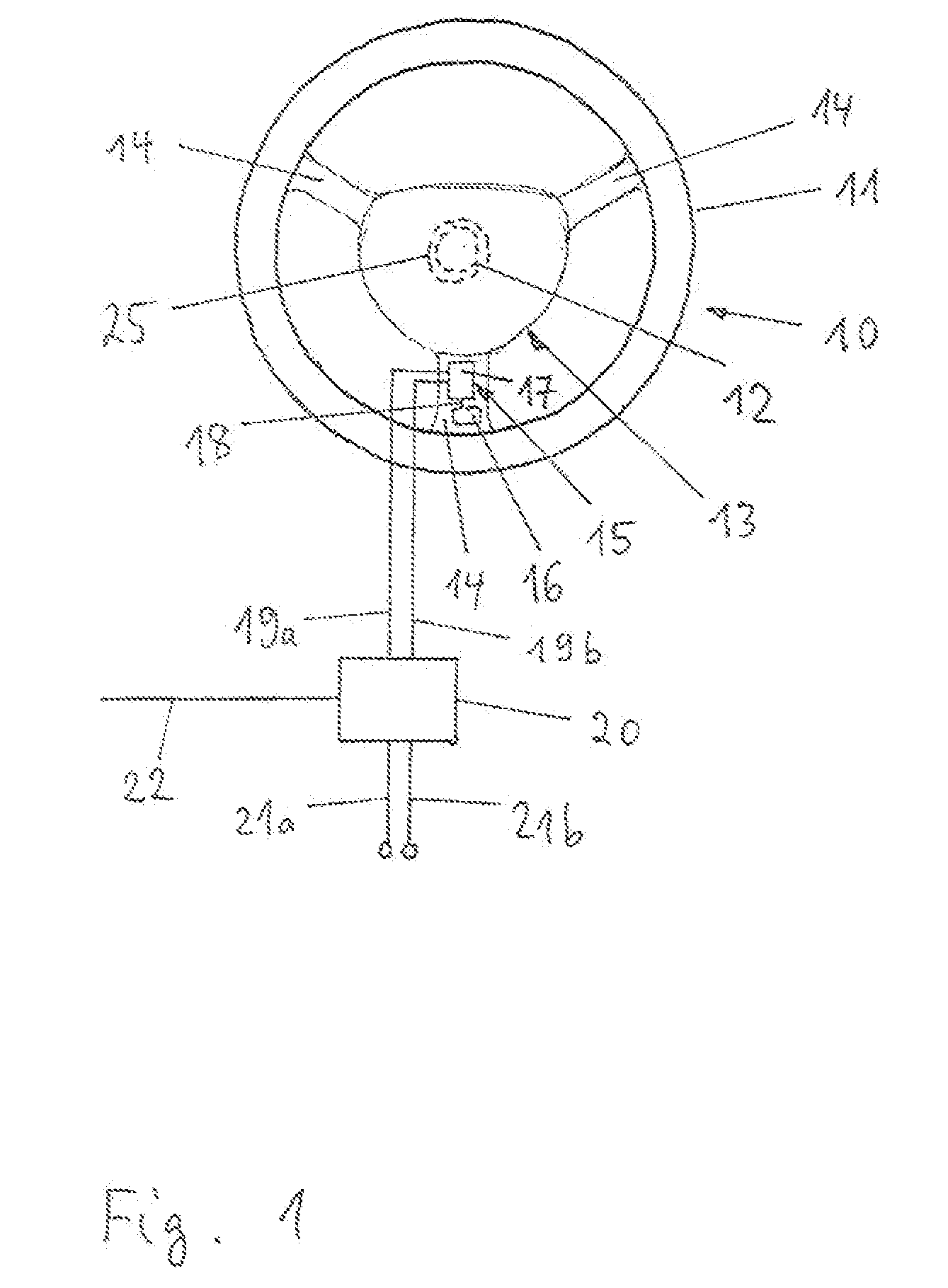
[0020]The steering wheel arrangement according to FIG. 1 is part of a motor vehicle and comprises a steering wheel 10 with a rim 11 which is connected to a steering wheel column 12 by means of a frame part 13 comprising spokes 14 and hub 25. A vibration unit 15 is connected to the frame part 13, in particular to one of the spokes 14. The vibration unit 15 comprises an electric DC motor 17 and a mass 16 eccentrically connected to the rotation axis 18 of the motor 17.

[0021]The electric motor 17 is connected via supply lines 19a and 19b to an electric control circuit 20 which is connected via supply lines 21a and 21b to an on-board power supply. Furthermore, the control circuit 20 is connected to receive data signals in particular via an on-board data bus 22.

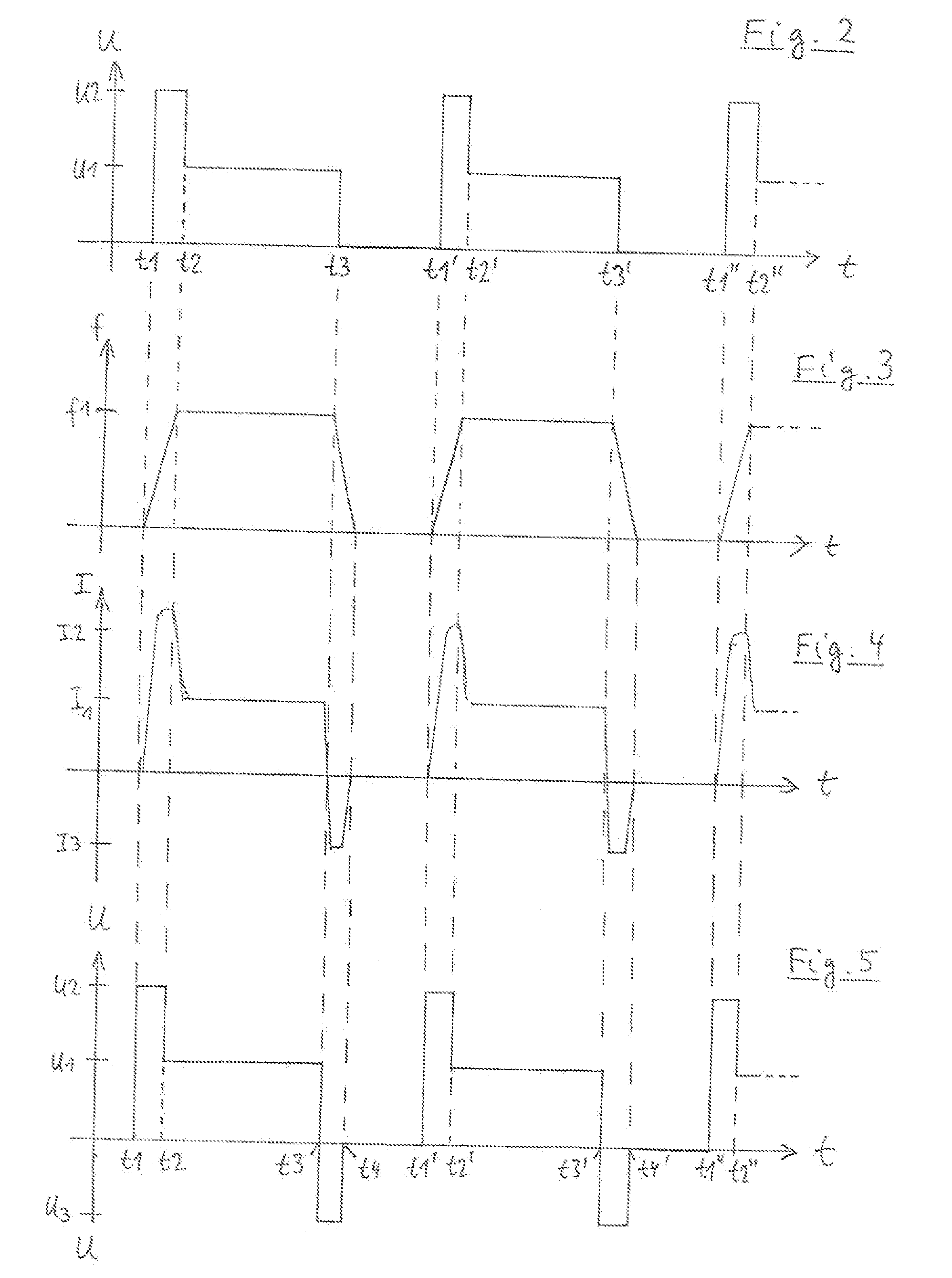
[0022]FIGS. 2 and 5 show voltage waveforms which the control circuit 20 applies to the electric motor 17 via the supply lines 19a and 19b in different voltage control embodiments. FIGS. 4 and 6 show the current flowing through the ...


PUM


Abstract

A driver alert system for the steering wheel of a motor vehicle. The system comprises an electric motor, an eccentric mass connected to the electric motor, and a control circuit for providing electric supply to the electric motor in response to an alert activation signal The motor is controlled by the control circuit to an operation level of voltage during a portion of a vibration period with a non-vibration period following the vibration period, and the motor is over or under-controlled with respect to the operation range at the beginning or end of said vibration period.

Description

CROSS REFERENCE TO RELATED APPLICATION[0001]This application claims priority to DE 20 2007 014209.0, filed Oct. 10, 2007.FIELD OF THE INVENTION[0002]The invention relates to a driver alert system for the steering wheel of a motor vehicle,BACKGROUND OF THE INVENTION[0003]A driver alert system is known, for example, as described by BP 0 856 432 A2 and US 2003 0197601 A1.[0004]When the driver alert system of the prior art is activated by supplying a voltage to the electric motor in order to cause vibrations in the steering wheel rim, the rotation frequency of the motor may accelerate only slowly and under negative circumstances may even be trapped at a resonance frequency of the steering wheel column. This could be overcome by using a stronger electric motor which however would require more space and leads to an increase of costs. Similarly, when the electric motor is stopped at the end of a vibration period, the motor may decelerate only slowly.[0005]It is the object of the invention ...

Claims


Application Information

Patent Timeline
Patent Type & Authority Applications(United States)
IPC IPC(8): G08B6/00
CPCB60W50/16B62D15/029B62D1/046
Inventor LEMASSON, PASCALCOURTY, JULIENVINCENT, PHILIPPE
Owner AUTOLIV DEV AB
Why Eureka
Try Eureka