

Illumination device and liquid crystal display device
- Summary
- Abstract
- Description
- Claims
- Application Information
AI Technical Summary
Benefits of technology
Problems solved by technology
Method used
Image

Examples
embodiment 1
Preferred Embodiment 1
[0053]The following explains a preferred embodiment of the present invention, with reference to FIGS. 1 through 6.
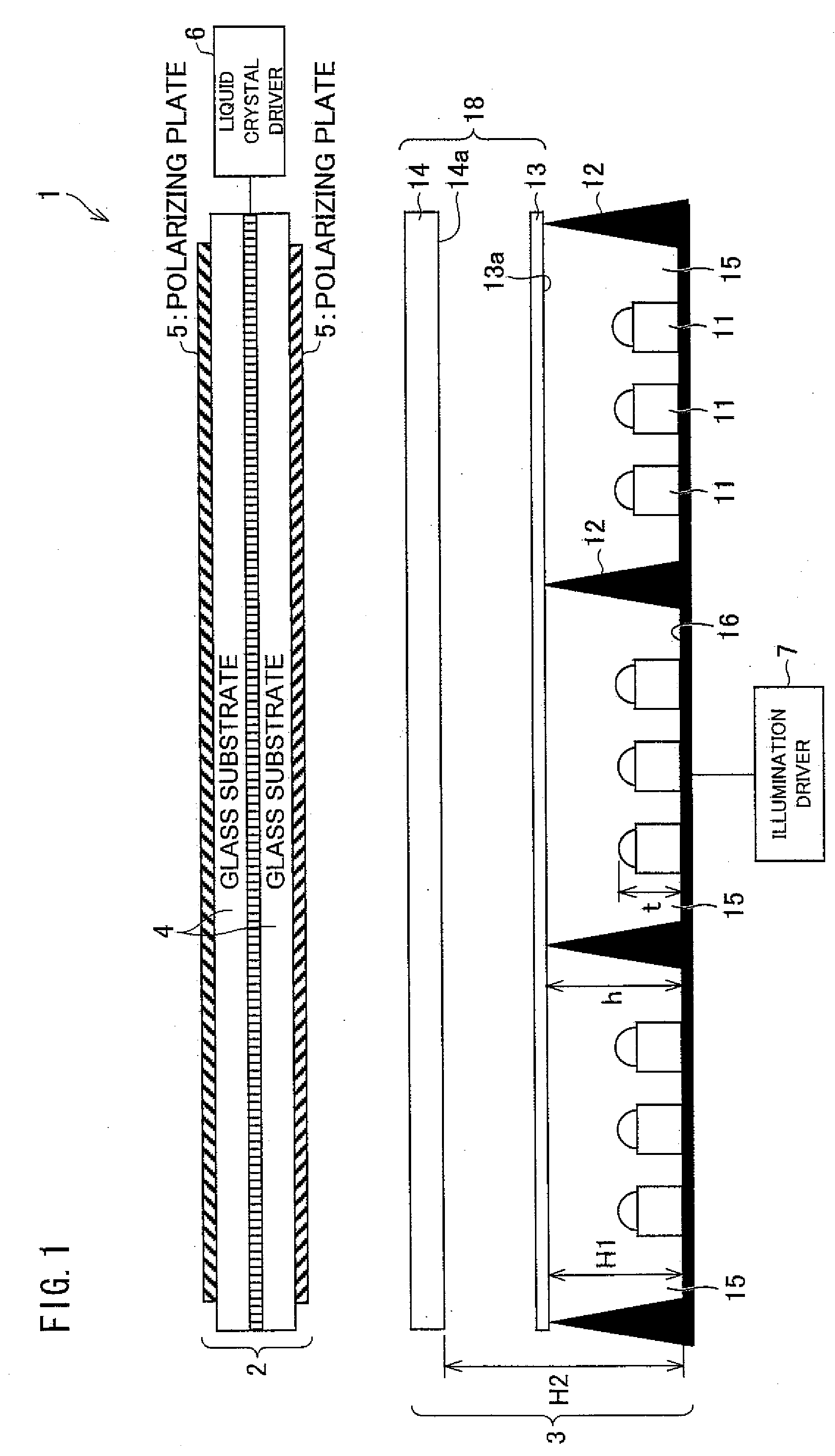
[0054]FIG. 1 is a diagram illustrating a schematic configuration of a substantial portion of a liquid crystal display device. As illustrated in FIG. 1, a liquid crystal display device 1 of Preferred Embodiment 1 of the present invention includes a liquid crystal panel 2, a liquid crystal driver 6, a backlight device 3 that is an illumination device, and an illumination driver 7.
[0055]The liquid crystal panel 2 has an arrangement including a pair of glass substrates 4 that are bonded each other at respective peripheries, and a pair of polarizing plates 5 that are provided respectively on outer surfaces of the respective glass substrates 4. Between the glass substrates 4, a liquid crystal layer is sealed and a color filter layer, a TFT array, and the like are formed, though not specifically illustrated.
[0056]In a case where the liquid crystal panel 2 ...
second preferred embodiment 2
[0084]The following explains another preferred embodiment of the present invention, with reference to FIGS. 7 and 8.
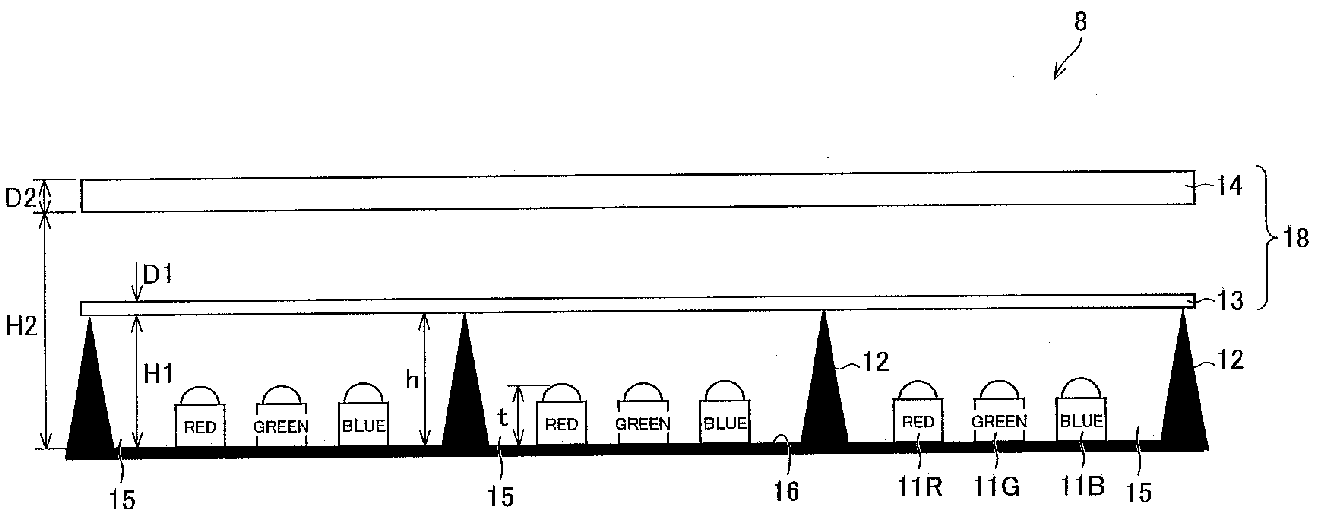
[0085]FIG. 7 is a diagram illustrating a schematic configuration of a substantial portion of a backlight device in a liquid crystal device of the present preferred embodiment. FIG. 8 is a plan view illustrating a substantial portion of a backlight device 8.
[0086]The liquid crystal display device of Preferred Embodiment 2 is different from a liquid crystal display device 1 of Preferred Embodiment 1 in that the liquid crystal display device of Preferred Embodiment 2 includes the backlight device 8 in lieu of the backlight device 3. The backlight 8 is different from the backlight device 3 in light sources provided on a light source disposition surface 16.
[0087]That is, though the backlight device 3 includes a plurality of white light sources 11, the backlight device 8 has an arrangement in which a plurality of red light sources 11R, a plurality of green light sources 11G,...
example 1
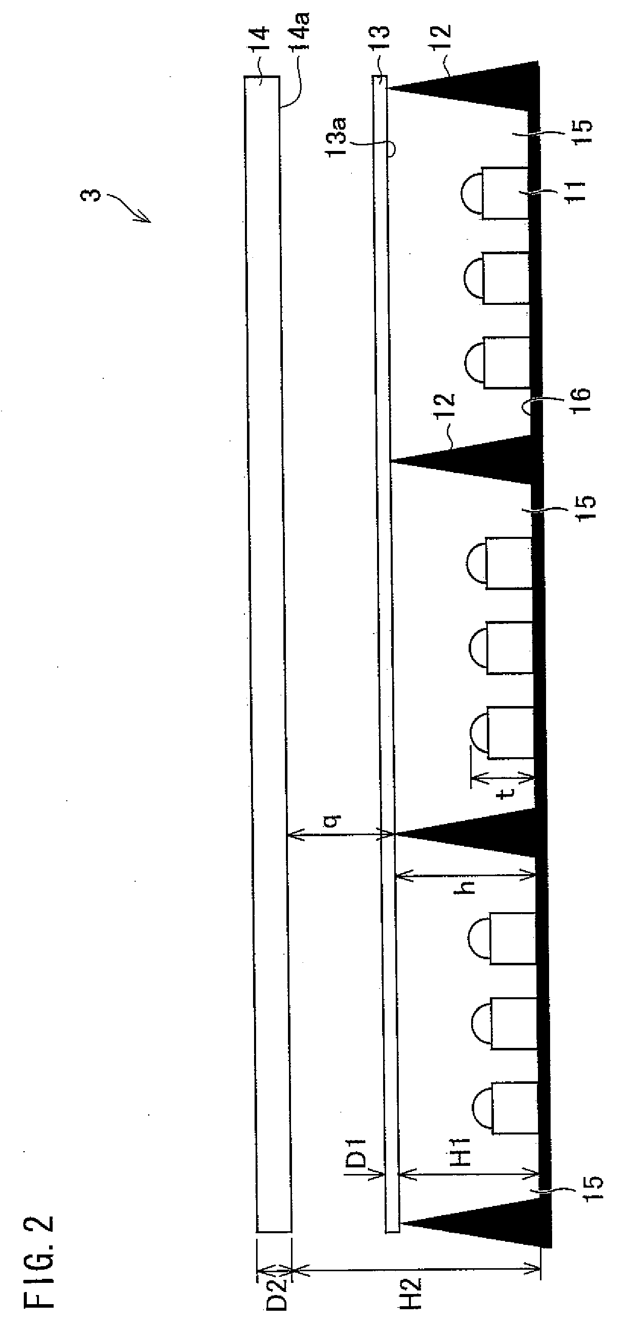
[0099]The following explains one example of a backlight device 3 of Preferred Embodiment 1. In an arrangement of the backlight device 3, NCCW022S (part number) fabricated by Nichia Corporation was used as each of a plurality of light sources 11. A size of the light source was φ 10 mm×10 mm (height). As a first light diffusing member 13, OPALUS BS-01 (product name) fabricated by Keiwa Inc. was used. As a second light diffusing member 14, CL AREX DR-IIIC DR-60C (product name) fabricated by Nitto Resin Corporation was used. Regarding the OPALUS that was used as the first diffusing member 13, a thickness D1 was 0.125 (mm) and a Haze ratio was 87(%). On the other hand, regarding the CLAREX DR-IIIC DR-60C that was used as the second diffusing member 14, a thickness D2 was 2.0 (mm) and a Haze ratio was 96(%).
[0100]A height h of a partition wall 12 from a light source disposition surface 16 was arranged to be 25 (mm). The first light diffusing member 13 was arranged so as to be in touch wit...
PUM
 Abstract
Description
Claims
Application Information