
Battery pack and method of fabricating the same

Inactive Publication Date: 2009-04-16
SAMSUNG SDI CO LTD
View PDF5 Cites 27 Cited by
  • Summary
  • Abstract
  • Description
  • Claims
  • Application Information

AI Technical Summary

Benefits of technology

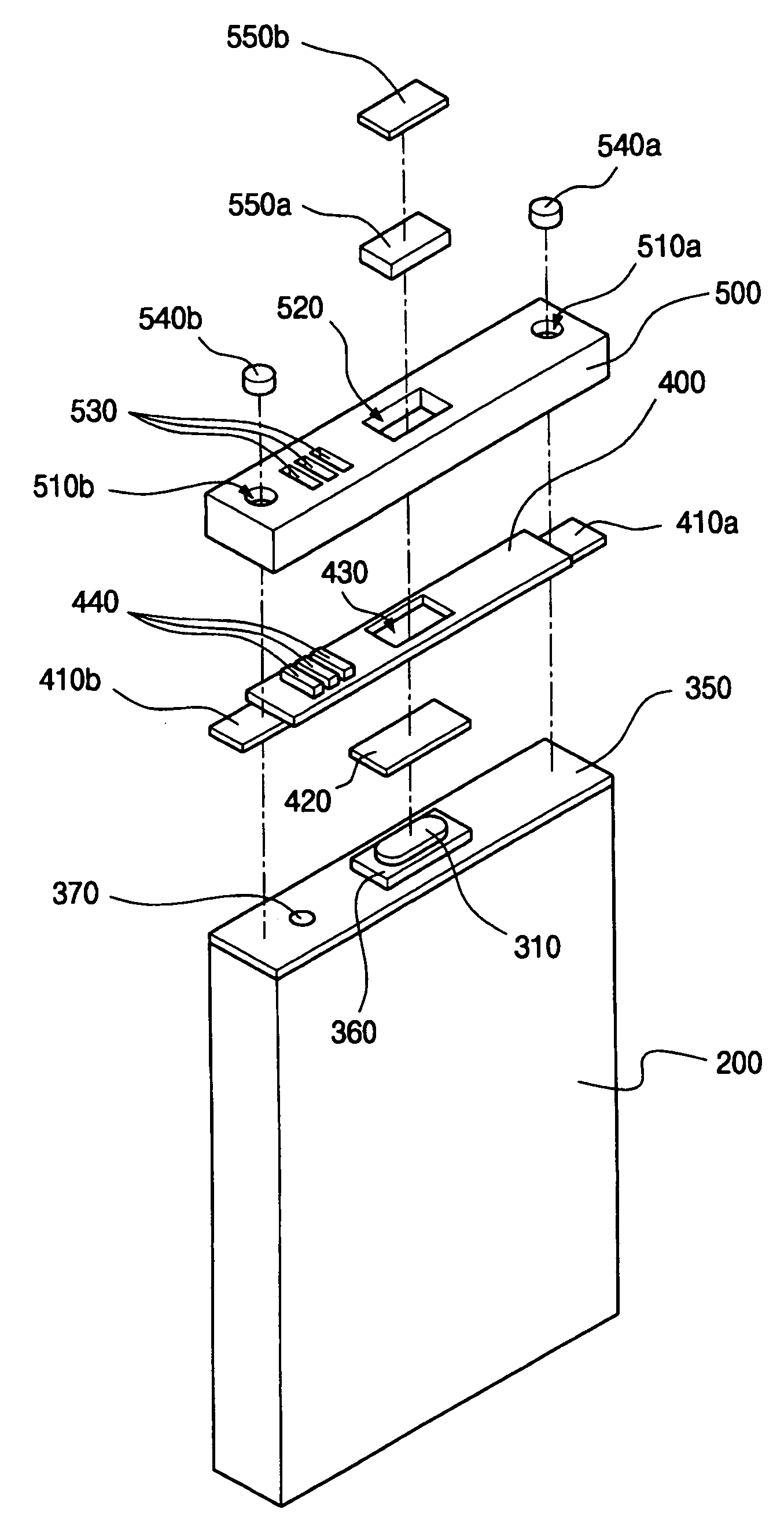
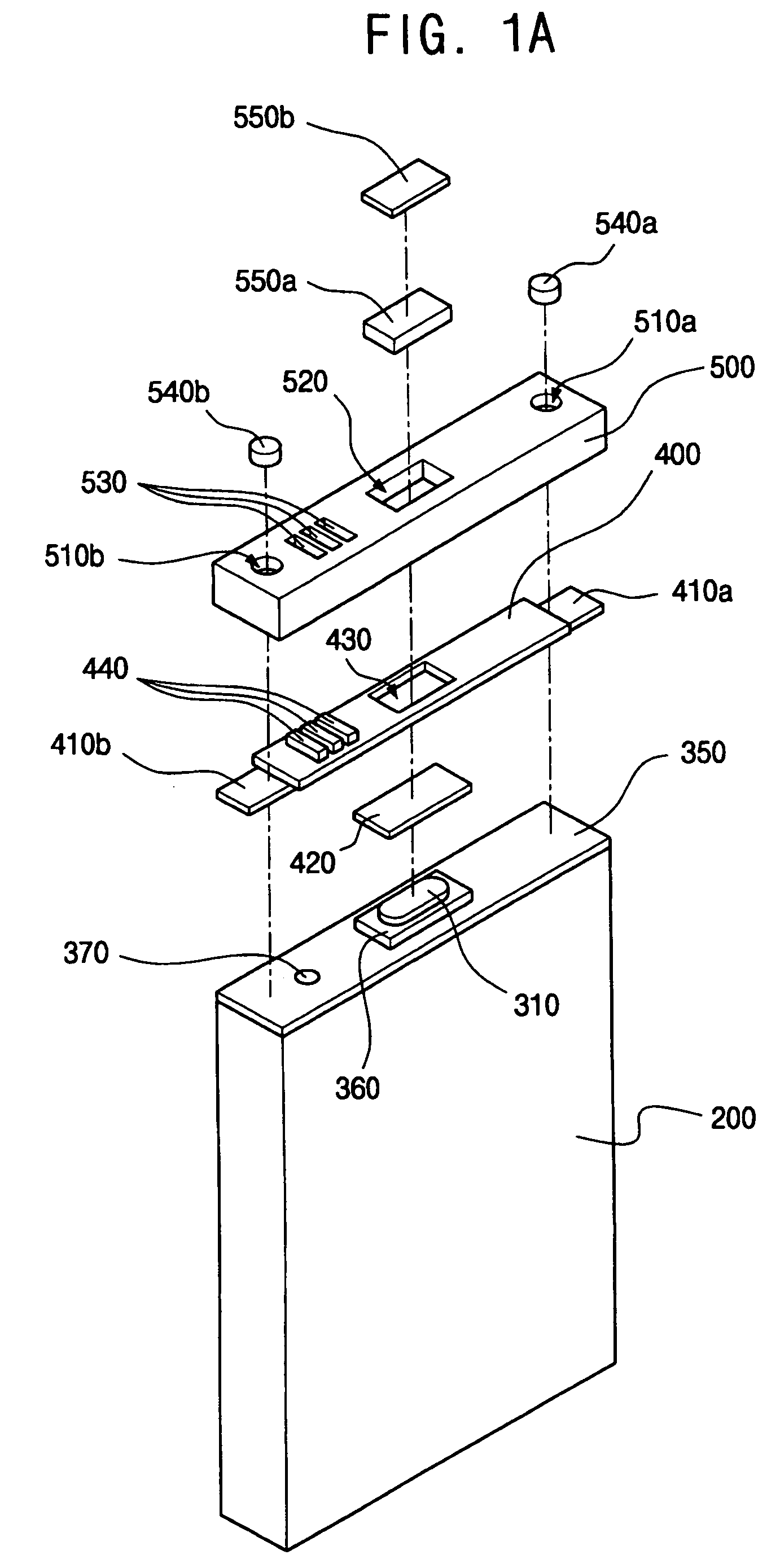
[0010]The present invention provides a battery pack and a method of fabricating the same, capable of reducing the entire length of the battery pack, by eliminating the need for the L-shaped electrical terminals.
[0011]In addition, the present invention provides a battery pack and a method of fabricating the same, capable of simplifying a connection structure between a bare cell and a protection circuit board to reduce component and process costs.

Problems solved by technology

However, when using the PTC, space and expense are required for forming an electrical terminal of the PTC for forming a contact between the PTC and the electrode terminal and between the PTC and the electrical terminal of the protection circuit board.
That is, as described above, it can be difficult to provide both a small size and a large capacity secondary battery due to the space required to form the electrical terminal of the PTC, the vertical parts of the L-shaped terminal, and so on.
In addition, in order to insulate the entire PTC, including the electrical terminal, from the cap plate, double-sided insulating tape or the like needs to be adhered to the cap plate, thereby increasing material and process costs.

Method used


Image

  • Battery pack and method of fabricating the same
  • Battery pack and method of fabricating the same
  • Battery pack and method of fabricating the same

Examples


first embodiment

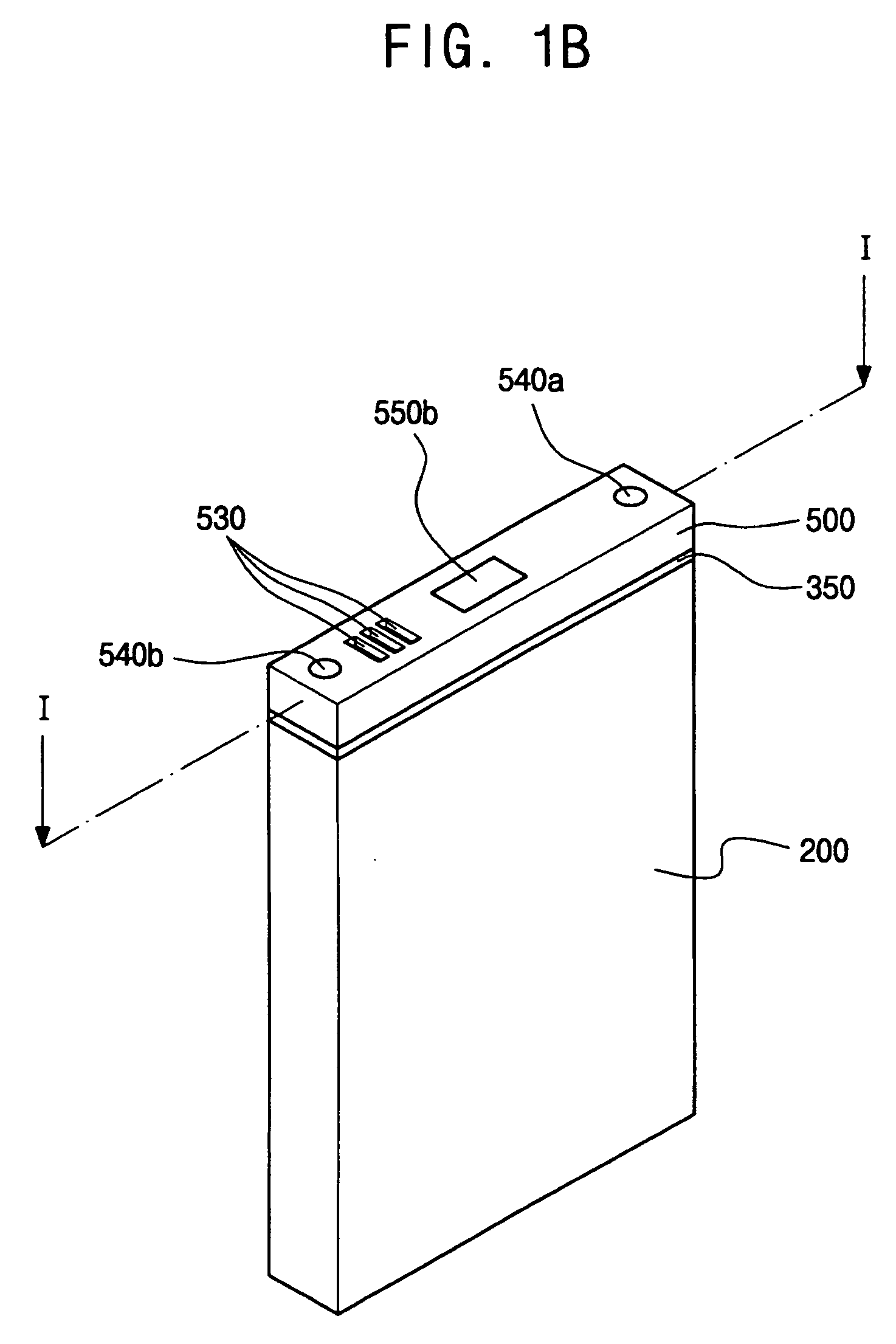
[0052]Turning now to FIG. 2, FIG. 2 is a cross-sectional view of a modification of a battery pack in accordance with a first exemplary embodiment of the present invention. The modified battery pack can have the same constitution as the first embodiment, except for the following description, and therefore, descriptions of components having the same constitution as that of FIGS. 1A through 1C will not be repeated.

[0053]As described above, in the first embodiment, the protection circuit board includes the metal tabs arranged at both ends thereof. Here, one of the metal tabs can be a lead tab electrically connected to the protection circuit board to electrically connect the cap plate to the protection circuit board, and the other of the metal tabs can be a dummy tab electrically insulated from the protection circuit board. The modification of the first embodiment in accordance with the present invention relates to the lead tab.

[0054]Referring to FIG. 2, the protection circuit board incl...

second embodiment

[0061]Referring to FIG. 3B, the battery pack in accordance with the first modification of the present invention includes a case having first apertures 710a and 710b that narrow from an upper side to a lower side thereof, i.e., have a tapered side surface. This tapered aperture sidewall profile is to prevent damage to the case due to an incidence angle of the laser welding during the laser welding process for electrically connecting the protection circuit board to the bare cell after coupling the protection circuit board to the case. Although the incidence angle of the laser welding may not be perpendicular to the cap plate due to a process error, it is possible to prevent damage to the case due to the laser by tapering the sidewalls of the apertures through which the laser welding occurs. In addition, a taper angle θ of apertures 710a / 710b can have an angle of 5 to 30 degrees with respect to a vertical cross-section of the cap plate.

[0062]When the taper angle θ is less than 5° and a...


PUM

PropertyMeasurementUnit
Angleaaaaaaaaaa
Thicknessaaaaaaaaaa
Electrical resistanceaaaaaaaaaa

Abstract

A battery pack and a method of fabricating the same. The battery pack includes a bare cell including an electrode terminal, a protection circuit board electrically connected to the bare cell, the protection circuit board including a plurality of metal tabs arranged at opposite ends thereof, and a case surrounding the protection circuit board, the case being perforated by a plurality of first apertures arranged at locations that correspond to ones of the plurality of metal tabs. The method includes arranging a bare cell having a cap plate and an electrode terminal passing through a terminal aperture in the cap plate, electrically connecting a protection circuit board to the bare cell, the protection circuit board having metal tabs arranged at both ends thereof and arranging a case to surround the protection circuit board, the case being perforated by a plurality of first apertures that are arranged at locations that correspond to ones of the metal tabs.

Description

CLAIM OF PRIORITY[0001]This application makes reference to, incorporates the same herein, and claims all benefits accruing under 35 U.S.C. §119 from an application earlier filed in the Korean Intellectual Property Office on 15 Oct. 2008 and there duly assigned Serial No. 10-2007-0103499.BACKGROUND OF THE INVENTION[0002]1. Field of the Invention[0003]The present invention relates to a battery pack having metal tabs arranged at both ends of a protection circuit board and a case having apertures arranged at a location that corresponds to the metal tabs, and a method of fabricating the same.[0004]2. Description of the Related Art[0005]Recently, various compact handheld electronic / electrical devices, such as cellular phones, notebook computers, camcorders, and so on, have been widely developed and produced. The handheld electronic / electrical devices include a battery pack installed therein to operate the same without a separate power source. The battery pack can be classified into a nick...

Claims


Application Information

Patent Timeline
IPC IPC(8): H01M10/02H01M10/04H01M50/534H01M50/536H01M50/538H01M50/553H01M50/562H01M50/566
CPCH01M10/058H01M10/425Y02E60/122H01M10/052H01M2/348H01M2/30H01M2/263Y10T29/49108Y02E60/10H01M50/538H01M50/581Y02P70/50H01M50/553H01M50/562H01M50/534H01M50/536H01M50/566H01M50/202H01M50/284H01M10/4257H01M50/557H01M50/247H01M50/103H01M2200/106H01M2220/30
Inventor BYUN, JEONG-DEOKSEO, KYUNG-WONKWON, YONG-GEOL
Owner SAMSUNG SDI CO LTD
Learn More