Work transfer system, route setting method, and route setting program

a work transfer and route setting technology, applied in the field of work transfer technique, can solve the problems of not always optimal shortest route, and achieve the effect of flexible handling of the change in system layou

Inactive Publication Date: 2009-04-16
HIRATA & CO LTD
View PDF10 Cites 44 Cited by
  • Summary
  • Abstract
  • Description
  • Claims
  • Application Information

AI Technical Summary

Benefits of technology

[0006]It is therefore an object of the present invention to implement efficient work transfer capable of flexibly coping with a change in system layout.

Problems solved by technology

However, when a mass of works are transferred in parallel, interference between the transferred works can cause congestion, and the shortest route is not always optimum.

Method used


Image

  • Work transfer system, route setting method, and route setting program
  • Work transfer system, route setting method, and route setting program
  • Work transfer system, route setting method, and route setting program

Examples


Embodiment Construction

Layout

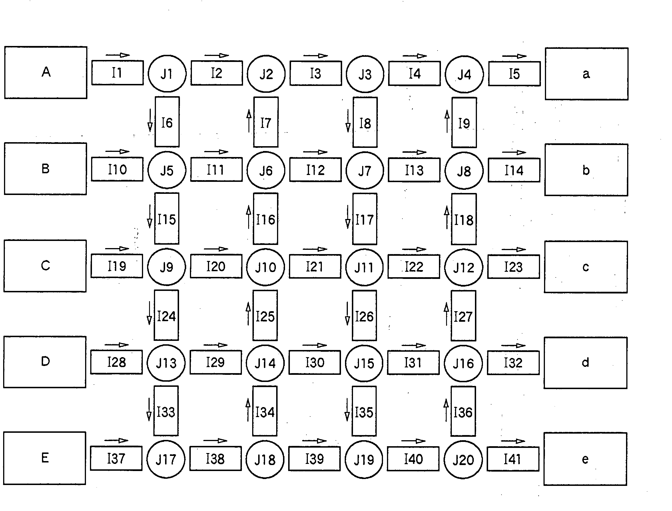
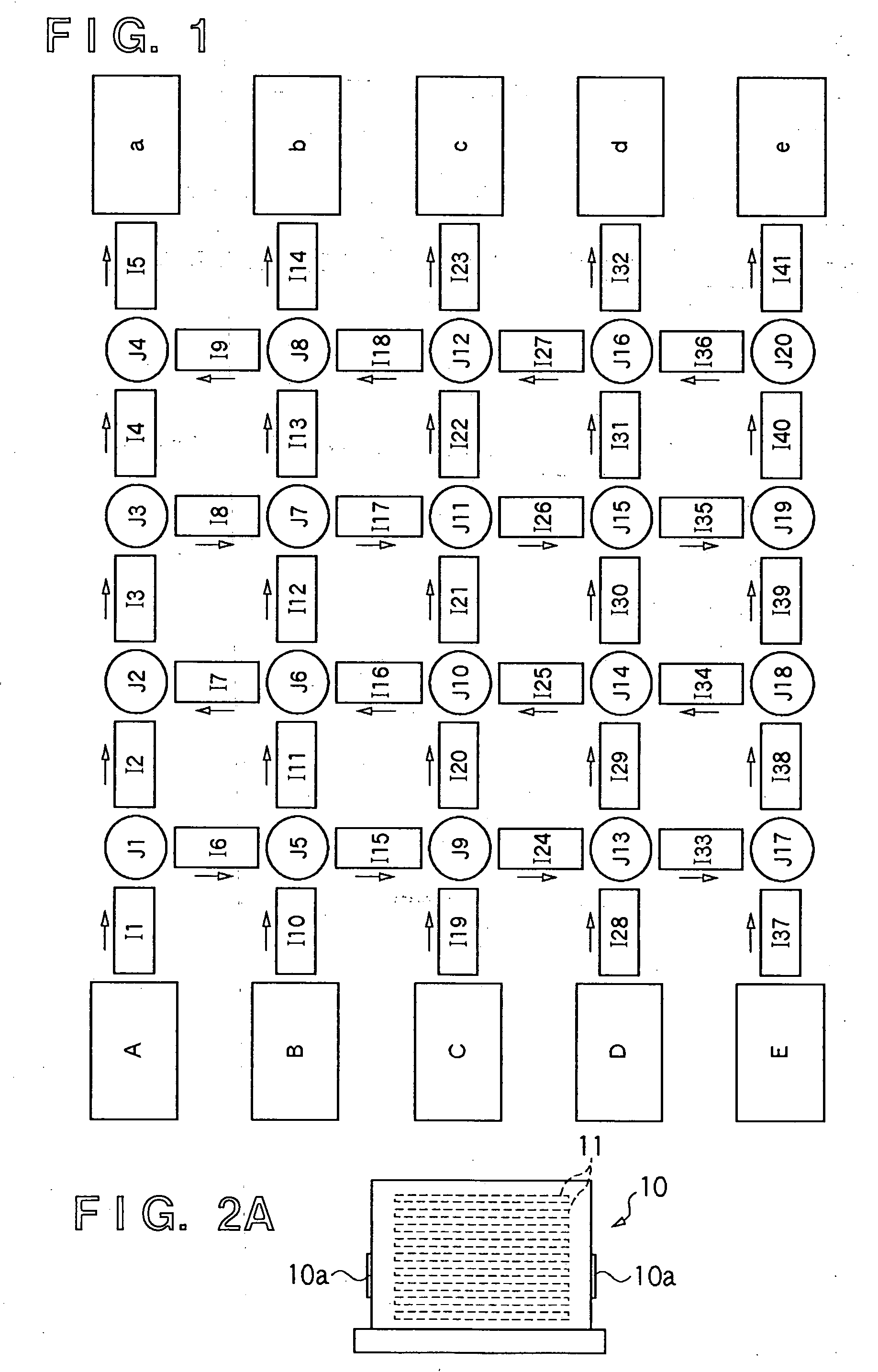
[0027]FIG. 1 is a view showing the layout of work transfer units in a work transfer system according to an embodiment of the present invention. Referring to FIG. 1, processing apparatuses A to E form an apparatus group and execute predetermined processes for a transfer target work. In this embodiment, each of the processing apparatuses A to E serves as a work loading place to work transfer units I1 to I41 and J1 to J20 (to be collectively referred to as work transfer units I and J). Processing apparatuses a to e also form an apparatus group and execute predetermined processes for a transfer target work. In this embodiment, each of the processing apparatuses a to e serves as a work unloading place from the work transfer units I and J.

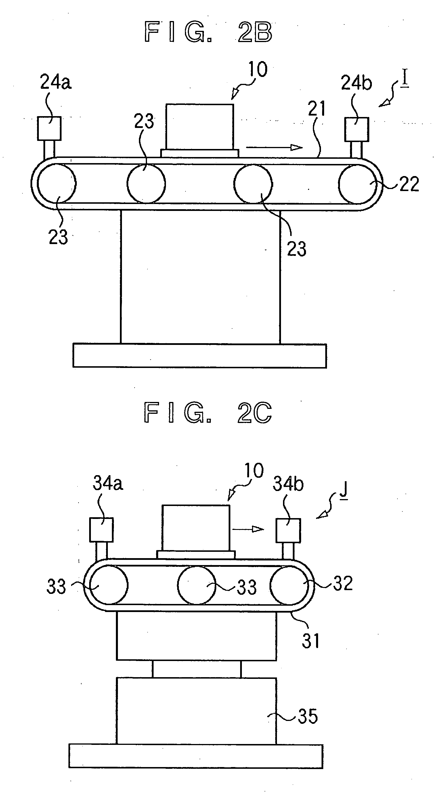
[0028]FIG. 2A is a schematic view of a pod 10 as a transfer target of this embodiment. In this embodiment, substrates 11 are transferred as works. Assume that a plurality of substrates 11 are stored in every pod 10 and transferred. The pod 10 has a...


PUM


Abstract

A route setting method according to the present invention sets, in a work transfer system including a plurality of work transfer units which connect a plurality of loading places to a plurality of unloading places, a route of the work transfer units to pass a work between a planned loading place and a planned unloading place which are required to transfer the work in the plurality of loading places and the plurality of unloading places. The route setting method includes the steps of setting, based on layout information representing a layout of the plurality of work transfer units, a plurality of candidates of the route between the planned loading place and the planned unloading place, and selecting, based on a predetermined condition, one route from the plurality of candidates of the route set in the candidate setting step.

Description

TECHNICAL FIELD[0001]The present invention relates to a work transfer technique applicable to various kinds of production facilities.BACKGROUND ART[0002]In a production facility such as a semiconductor manufacturing system, a plurality of kinds of processes are executed for a substrate serving as a work. To do this, a production facility of this type requires transfer of a work between a plurality of processing apparatuses. Work transfer schemes are roughly classified into a system using an automatic guided vehicle (AGV) (e.g., Japanese Patent Laid-Open No. 2004-280213), a system using an aerial train, and a system using a permanently installed transfer unit such as a transferor belt.[0003]On the other hand, a production facility of this type requires improvement of the transfer efficiency so as to process a number of works. Improvement of the transfer efficiency depends on the transfer routes of individual works between the plurality of processing apparatuses. Japanese Patent Laid-...

Claims


Application Information

Patent Timeline
Patent Type & Authority Applications(United States)
IPC IPC(8): G06F17/00
CPCB65G1/0478B65G43/10B65G37/02G05B19/41895Y02P90/02Y02P90/60Y10S414/135
Inventor YOSHIKAWA, TAKERUUCHIMURA, KEIICHIHU, ZHENCHENGKANDABASHI, TSUGUMITSU
Owner HIRATA & CO LTD
Why Eureka
Try Eureka