Optical recording medium and recording method for optical recording medium

a recording medium and optical recording technology, applied in the field of optical recording medium and optical recording medium recording method, can solve the problems of insufficient recording structure, inability to synthesize dyes, insufficient storage reliability of recorded state, etc., and achieve high density and high-speed recording. , the effect of simple recording strategy

Inactive Publication Date: 2006-01-03
TDK CORPARATION
View PDF11 Cites 25 Cited by
  • Summary
  • Abstract
  • Description
  • Claims
  • Application Information

AI Technical Summary

Benefits of technology

[0014]The present invention has been accomplished in order to solve the above-described problems existing in prior art, and it is an object of the invention to provide a write-once optical recording medium which can perform a high-density and high-speed recording with a simple recording strategy, and can also highly maintain an adaptability to a low speed recording. Another object of the invention is to provide a recording method for the write-once optical recording medium. Further, the present invention is to provide an optical recording medium capable of performing not only a write-once recording but also a rewriting on the same optical recording medium which makes use of the above characteristics, and to provide a recording method for such an optical recording medium.
[0031]This means that when a recording is performed, it is allowed to adopt the simplest recording strategy as its recording strategy, such as an arrangement for switching a laser power having only two values including a write power and a bias power, also means that it is possible to flexibly deal with a linear velocity change from a low speed to a high speed only through an extremely simple adjustment.
[0032]As a result, although at a low cost, it is possible to perform a high density recording at a high speed, also a stabilized high density recording at a low speed. Therefore, it is possible to obtain an optical recording medium suitable for use as multimedia which is required to record large capacity information sometimes at a low speed and sometimes at a high speed. Further, such recording medium is suitable for use in CAV or ZCAV which performs a rotation control at a constant rotation angular velocity allowing a high speed transfer.

Problems solved by technology

However, such a recording structure has been found insufficient in its recording sensitivity when performing a high speed recording.
On the other hand, if the wavelength of a laser beam is made short in order to increase a recording density, there will be a problem that it is difficult to synthesize dyes which can be used with laser beams having wavelengths equal to or shorter than that of a blue light.
Hei 4-838, etc.) that recording layer can be formed by an inorganic material, none of conventional structures is suitable for high density or high speed recording, their storage reliability of recorded state is inadequate, and their playback durability is insufficient.
Further, although an optical recording medium, which has been treated such that its recording density has been improved in preference to other parameters, can be used to perform a recording by using CLV (Constant Linear Velocity) method, since a considerable amount of time is needed in controlling the rotational speed of the optical recording medium, such an optical recording medium is not suitable for use as a recording medium which is required to perform a high speed access and a high speed transfer.
However, a rewritable optical recording medium, in an aspect of “recording at a variable speed” as mentioned above, has a problem that its flexibility is low.
Since it is necessary to strictly control various factors such as a cooling speed related to time, a rewritable optical recording medium is difficult in adjusting its recording strategy when a recording transfer rate has been changed, and its flexibility with respect to a variable speed recording is extremely low.
Moreover, a rewritable optical recording medium is weak in preventing a data alteration which is possibly caused by an intentional action or a negligence.

Method used


Image

  • Optical recording medium and recording method for optical recording medium
  • Optical recording medium and recording method for optical recording medium
  • Optical recording medium and recording method for optical recording medium

Examples


example 1

[0080]Example Using Al and Sb as Main Component Metals.

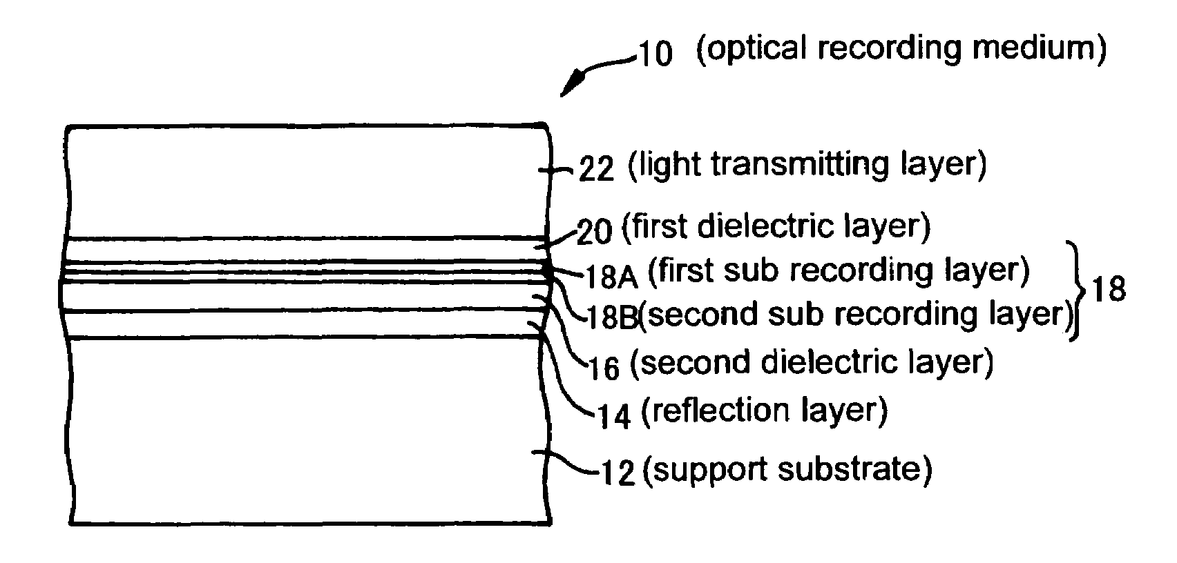
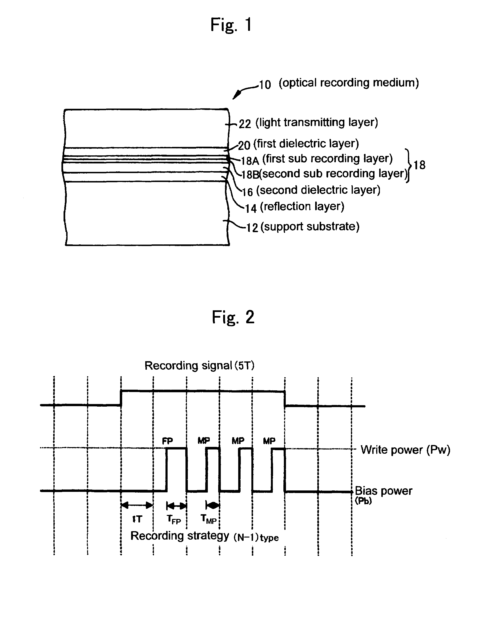
[0081]An optical recording medium was produced in accordance with an arrangement shown in FIG. 1, an evaluation was conducted on a variable transfer rate.

[0082]The support substrate 12 was formed by a polycarbonate substrate of 1.1 mm having groups formed thereon at group pitch of 0.32 μm, while the thickness of the light transmitting cover layer 22 was set at 100 μm.

[0083]Other layers were produced by sputtering under the following condition.

[0084]Electrostatic layer: ZnS+SiO2 (80:20 mol %)

[0085]First dielectric layer 20: 60 nm

[0086]Second dielectric layer 16: 105 nm

[0087]First sub recording layer 18A: AlCr (98:2 at. %) 4 nm

[0088]Second sub recording layer 18B: Sb 6 nm

[0089]Reflection layer 14: AgPdCu (98:1:1 at. %) 100 nm

[0090]Random signals were recorded and playback was evaluated by an evaluation apparatus whose laser beam has a wavelength of 405 nm and whose objective lens group has a numerical aperture NA of 0.85, using mo...

example 2

[0100]Example Using Si and Cu as Main Component Metals.

[0101]An optical recording medium was produced in accordance with an arrangement shown in FIG. 1, an evaluation was conducted on a variable transfer rate in the same manner as in Example 1.

[0102]A support substrate and a light transmitting cover layer were formed in the same manner as in Example 1.

[0103]Other layers were produced by sputtering under the following condition.

[0104]Electrostatic layer: ZnS+SiO2 (80:20 mol %)

[0105]First dielectric layer 20: 22 nm

[0106]Second dielectric layer 16: 28 nm

[0107]First sub recording layer 18A: Si 5 nm

[0108]Second sub recording layer 18B: Cu 6 nm

[0109]Reflection layer 14: AgPdCu (98:1:1 at. %) 100 nm

[0110]The strategy used in the recording was such that the lengths of pulses in (n−1) type were set at TFP: 0.4T, TMP: 0.3T.

[0111]A read power (Pr) and a bias power (Pb) were all set at 0.4 mW.

[0112]Others are the same as those in Example 1, such that the recording transfer rate was changed, an ...

example 3

Example of Multilayer

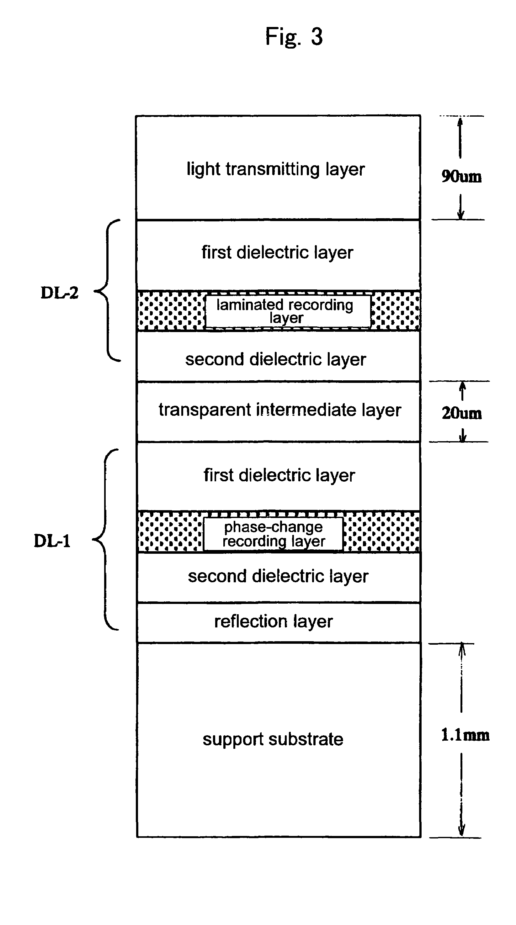
[0133]An optical recording medium was made in accordance with an arrangement shown in FIG. 3, and an evaluation was conducted on the recording and playback of the multilayered recording medium.

[0134]This sample has two data layers separated from each other by a transparent intermediate layer. A laser beam is incident on the data layers from a light transmitting layer side so as to perform recording or playback on the two data layers.

[0135]The support substrate was formed by a polycarbonate substrate of 1.1 mm having groups formed thereon at group pitch of 0.32 μm.

[0136]The transparent intermediate layer, after being coated with an ultraviolet-setting resin by means of spin coating, is pressed by a stamper having a group pattern, and at the same time irradiated by an ultraviolet light so as to be cured and thus formed into a predetermined shape. Incidentally, this group pattern is the same as the group pattern on the support substrate, while the thickness of the ...


PUM

PropertyMeasurementUnit
wavelengthaaaaaaaaaa
thicknessaaaaaaaaaa
thicknessaaaaaaaaaa

Abstract

To obtain an optical recording medium capable of recording at various recording transfer rates from a low speed to a high speed, by using a simple recording strategy.A recording layer 18 of a write-once optical recording medium capable of recording from a low speed to a high speed is formed by laminating a first sub recording layer 18A and a second sub recording layer 18B each containing a metal as its main component. When the recording layer (laminated recording layer) 18 is irradiated with a laser beam having a wavelength equal to or shorter than a blue wavelength by using a recording strategy comprising only a ratio of write power to bias power, the main component metals contained in the first and second sub recording layers 18A, 18B diffuse and are thus mixed together, forming the sub recording layers into a single layer by means of such mixing and forming recording marks whose reflectance have been irreversibly changed. Since the recording mark formation process does not need to select a recording strategy, it is possible to obtain many subordinate advantages such as a variable speed recording.

Description

TECHNICAL FIELD[0001]The present invention relates to an optical recording medium and a recording method for the optical recording medium.BACKGROUND ART[0002]Now, in the market of optical recording medium there have been distributed rewritable optical recording media and so-called write-once optical recording media which are not rewritable. A rewritable optical recording medium, as meant by the word “rewritable,” allows data to be written therein again and again, so that it is possible for the same optical recording medium to be used repeatedly in recording only required data. On the other hand, a write-once optical recording medium is not rewritable and thus characterized by a feature that “data will never be altered,” thereby making itself useful in data distribution, storage, or backup.[0003]In recent years there has been a demand for an optical recording medium which is capable of performing a stable high-density and high-speed recording when being used as multimedia for recordi...

Claims


Application Information

Patent Timeline
Patent Type & Authority Patents(United States)
IPC IPC(8): B32B3/02G11B7/0045B41M5/26G11B7/006G11B7/125G11B7/24G11B7/243
CPCG11B7/0062G11B7/24067G11B7/243G11B7/24038Y10T428/21G11B7/254G11B7/257G11B7/258G11B7/253
Inventor MIZUSHIMA, TETSUROMISHIMA, KOJIYOSHINARI, JIRO
Owner TDK CORPARATION
Why Eureka
Try Eureka