Method and apparatus for incrementally computing criticality and yield gradient

a technology of criticality and yield gradient, applied in the field of statistic timing analysis, can solve problems such as inefficient methods for optimizing large circuits

Active Publication Date: 2009-04-16
SIEMENS PROD LIFECYCLE MANAGEMENT SOFTWARE INC
View PDF23 Cites 20 Cited by
  • Summary
  • Abstract
  • Description
  • Claims
  • Application Information

AI Technical Summary

Problems solved by technology

The computational intensity of conventional methods for computing criticality and yield gradient, however, render such methods inefficient for use in optimizing large circuits.

Method used


Image

  • Method and apparatus for incrementally computing criticality and yield gradient
  • Method and apparatus for incrementally computing criticality and yield gradient
  • Method and apparatus for incrementally computing criticality and yield gradient

Examples


Embodiment Construction

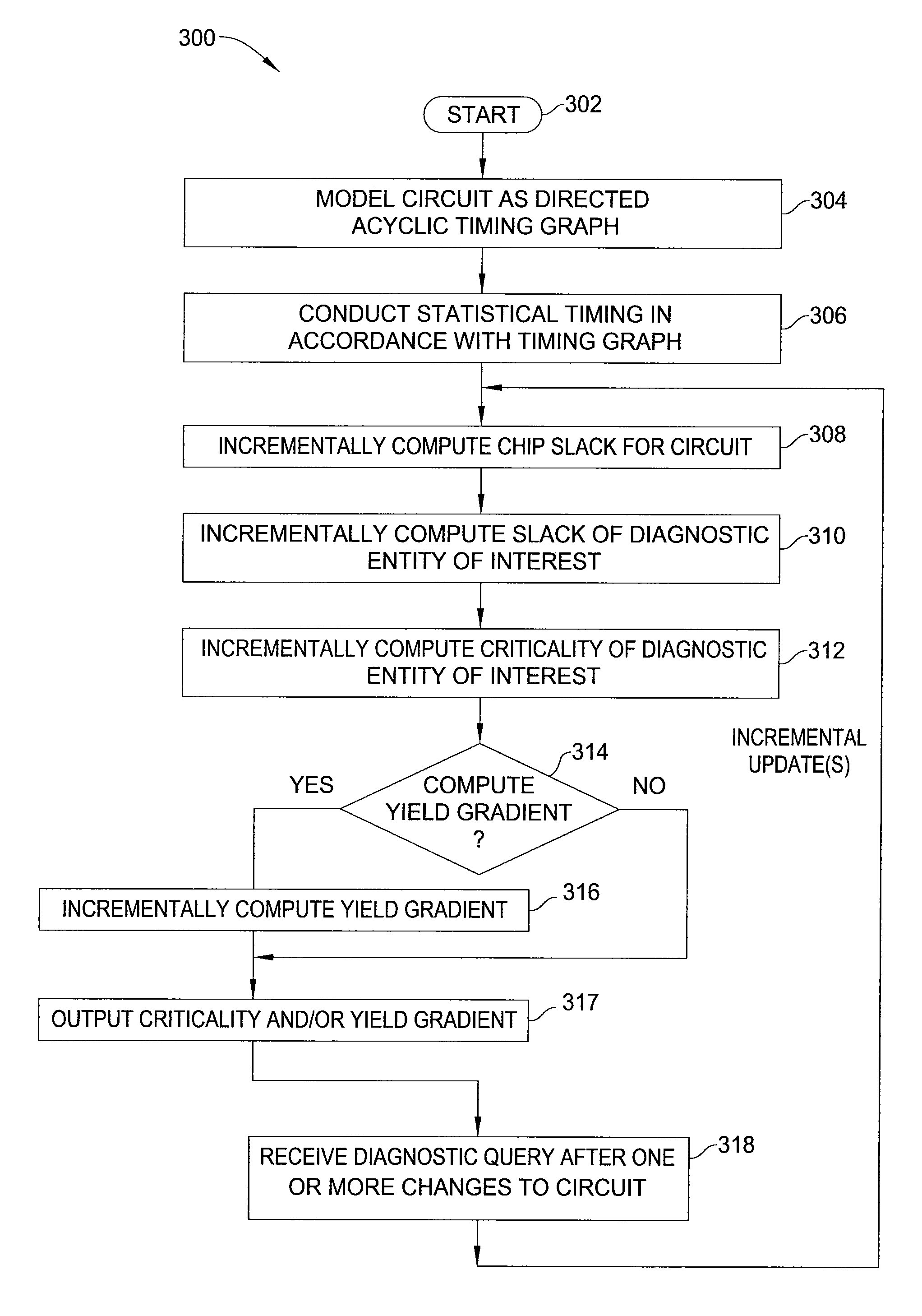
[0017]In one embodiment, the present invention is a method and apparatus for incrementally computing criticality and yield gradient. One embodiment of the invention represents the circuit as a directed acyclic timing graph, and then computes the criticality of nodes, edges, and paths of the timing graph (the term “diagnostic entity”, as used herein, refers to a node, edge, or path of the timing graph). Further embodiments of the invention compute the gradient of the parametric yield of the circuit with respect to components of the delay of each diagnostic entity. Embodiments of the present invention compute criticality and yield gradient in an incremental manner, thereby minimizing the computational intensity of timing analyses.

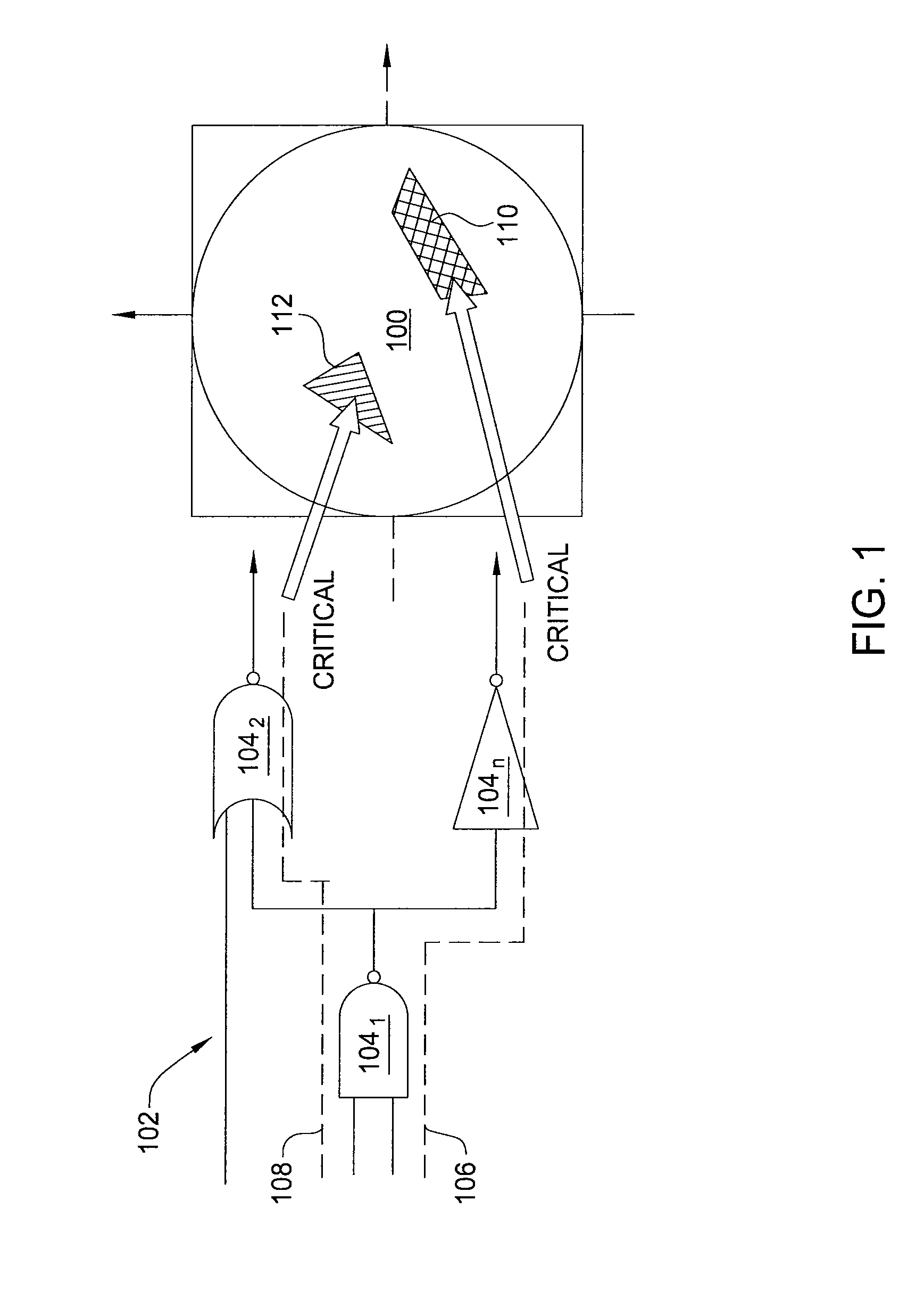
[0018]FIG. 1 is a schematic diagram illustrating the concept of “criticality”, as used within the context of the present invention. Specifically, FIG. 1 illustrates a netlist 102 corresponding to a chip design manufactured in a two-dimensional space of manufa...


PUM


Abstract

In one embodiment, the invention is a method and apparatus for incrementally computing criticality and yield gradient. One embodiment of a method for computing a diagnostic metric for a circuit includes modeling the circuit as a timing graph, determining a chip slack for the circuit, determining a slack of at least one diagnostic entity, and computing a diagnostic metric relating to the diagnostic entity(ies) from the chip slack and the slack of the diagnostic entity(ies).

Description

BACKGROUND OF THE INVENTION[0001]The present invention relates generally to design automation, and relates more particularly to statistical timing analysis.[0002]As complementary metal-oxide-semiconductor (CMOS) technology continues to scale down to forty-five nanometers and beyond, process variation effects become increasingly important, and must be taken into account, for design closure. Statistical static timing analysis (SSTA) is commonly used in the timing of chip designs to account for these process variation effects.[0003]Two important diagnostic metrics obtained from SSTA are criticality and yield gradient. Criticality and yield gradient provide valuable information that can be used to guide timing optimization and timing-driven physical synthesis. The computational intensity of conventional methods for computing criticality and yield gradient, however, render such methods inefficient for use in optimizing large circuits.[0004]Thus, there is a need in the art for an efficien...

Claims


Application Information

Patent Timeline
Patent Type & Authority Applications(United States)
IPC IPC(8): G06F17/50
CPCG06F17/5045G06F17/5031G06F30/3312G06F30/30G06F2111/08G06F30/3315
Inventor VISWESWARIAH, CHANDRAMOULIXIONG, JINJUNZOLOTOV, VLADIMIR
Owner SIEMENS PROD LIFECYCLE MANAGEMENT SOFTWARE INC
Why Eureka
Try Eureka