Engine rotation speed controller for working machine

a technology of rotating speed controller and working machine, which is applied in the direction of electric control, ignition automatic control, speed sensing governor, etc., can solve the problems of difficult to obtain stable controlled effect of the governor mechanism, engine is not provided with the governor mechanism, etc., to reduce the amount of throttle opening, reduce the effect of engine rotation speed and easy creation of control data

Inactive Publication Date: 2009-04-23
HONDA MOTOR CO LTD
View PDF3 Cites 11 Cited by
  • Summary
  • Abstract
  • Description
  • Claims
  • Application Information

AI Technical Summary

Benefits of technology

[0015]According to the first feature, in the increase process of the engine rotation speed, the engine rotation speed can be switched to the engine rotation control characteristic in which the ignition device is operated at the second ignition timing in which the amount of the advance angle is large upon reaching the region in which the throttle opening is large, and immediately increased. In the decrease process of the engine rotation speed by returning the throttle opening to the close side, the engine rotation speed is regarded to as reaching the region in which the throttle opening is small when engine rotation speed is higher than that switched to the second ignition timing in the increase process of the engine rotation speed. Then the engine rotation speed is returned to the first ignition timing in which the amount of the advance angle is small when the engine rotation speed is higher than that advanced to the second ignition timing in the increase process of the engine rotation speed. In this operation, in the decrease process of the engine rotation speed, the engine rotation speed can be decreased at the same throttle opening as that in the increase process of the engine rotation speed. The rotation speed returning operation to near idle can be performed while the operator hardly feel response delay due to decrease of the engine rotation speed according to the reduced amount of the throttle opening.
[0016]According to the second feature, the significant change of the engine rotation speed by mutual switching between the first ignition timing and the second ignition timing can be performed stepwise. The engine rotation speed at the time of changing the throttle opening can be smoothly changed.
[0017]According to the third feature, the engine rotation speed and the ignition timing are mapped so that control data can be easily created. The first rotation control characteristic at the first ignition timing and the characteristic performing advance or retardation stepwise between both may be mapped. Therefore the map can be easily created. When the number of rotation control characteristics is increased, the map can also be easily created.
[0018]According to the fourth feature, the function of fixing the throttle opening is provided. The function of substantially uniquely determining the engine rotation speed according to the throttle opening can be sufficiently exploited to maintain operation at a stable rotation speed with respect to load fluctuation.

Problems solved by technology

Therefore, the conventional governor mechanism is hard to obtain a stable controlled effect and a working machine is required to be made smaller and more lightweight.
Because of such situations, the engine is not provided with the governor mechanism in many cases.

Method used


Image

  • Engine rotation speed controller for working machine
  • Engine rotation speed controller for working machine
  • Engine rotation speed controller for working machine

Examples


Embodiment Construction

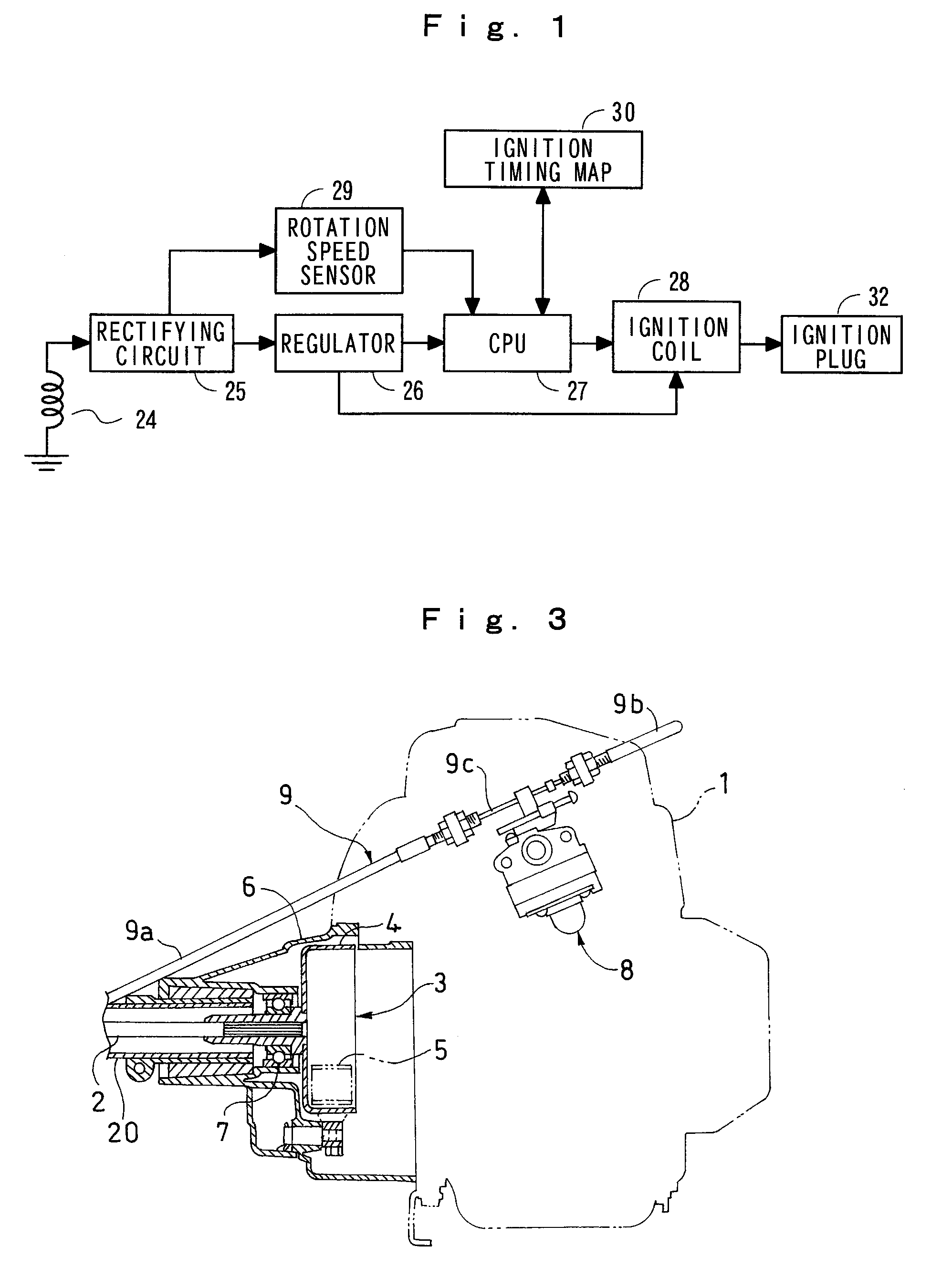
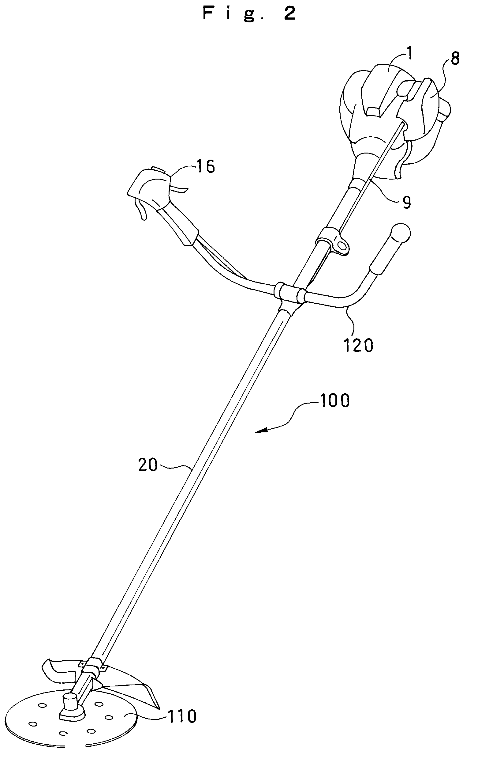
[0028]An embodiment of the present invention will be described below in detail with reference to the drawings. FIG. 2 is a perspective view of a mowing machine equipped with an engine including a rotation speed controller according to an embodiment of the present invention. FIG. 3 is a cross-sectional view of the front portion of the engine. FIG. 4 is a plan view of a carburetor. In FIG. 2, a mowing machine 100 has an engine 1, an operating sleeve 20 extended from the engine 1 and having at its edge a cutting blade 110, a handle 120 provided midway in the operating sleeve 20, and an operating device 16 serving also as a grip and provided at the right end of the handle 120. The mowing machine 100 also has a throttle cable 9 extended from the operating device 16 to a carburetor 8 of the engine. The engine 1 is an air-cooled four-stroke single-cylinder engine of a small type (e.g., the displacement is 25 cm3) preferable for the mowing machine 100.

[0029]In FIGS. 3 and 4, a transmission ...


PUM


Abstract

When an engine rotation speed in an engine for working machine without a governor mechanism is increase-and-decrease-controlled by switching ignition timings at a predetermined rotation speed, the response delay of the engine rotation speed with respect to the throttle opening operation is suppressed. The engine rotation speeds for switching the ignition timings are set to 4000 rpm and 5000 rpm. When the throttle opening is increased, a first ignition timing is advanced stepwise to a second ignition timing at the engine rotation speed of 4000 rpm so as to be switched to a rotation control characteristic C30 for high speed rotation. When the throttle opening is decreased, the second ignition timing is retarded stepwise to the first ignition timing at the engine rotation speed of 5000 rpm so as to be switched to a rotation control characteristic C05 for low speed rotation. The switching timing of the rotation control characteristic is different between at increase and decrease of the throttle opening. The difference can be reduced to a small amount ΔTH.

Description

TECHNICAL FIELD[0001]The present invention relates to a rotation speed controller of an internal combustion engine for working machine. More specifically, the present invention relates to an engine rotation speed controller which can control an engine rotation speed without having a governor mechanism, that is, mechanical speed control means.BACKGROUND ART[0002]In general, rotation speed of an engine for driving a working machine, such as a small-size versatile engine, is controlled to a rotation speed suitable for a load by opening control of a carburetor by a governor mechanism. There has been known the governor mechanism which moves a link mechanism by a centrifugal force corresponding to an engine rotation speed and transmits movement of the link mechanism to a throttle valve to perform throttle opening control. An engine used as the power source of a handheld mowing machine or blower is used at a relatively high rotation speed. Therefore, the conventional governor mechanism is ...

Claims


Application Information

Patent Timeline
Patent Type & Authority Applications(United States)
IPC IPC(8): F02P5/15
CPCF02B63/02Y02T10/46F02D31/002F02D37/02F02D2009/023F02D2011/102F02D2400/06F02P1/083F02P1/086F02P5/045F02P5/1502F02P5/1504F02P5/1556F02P9/005F02D11/02Y02T10/40
Inventor TAMAMOTO, RYUHEI
Owner HONDA MOTOR CO LTD
Why Eureka
Try Eureka