
Systems, methods, and apparatus for electrical filters and input/output systems

a technology of electrical filters and input/output systems, applied in the direction of printed circuit parts, electrical apparatus, printed inductance incorporation, etc., can solve the problems of difficult to maintain superconducting temperatures, especially difficult with i/o systems

Active Publication Date: 2009-04-23
D WAVE SYSTEMS INC
View PDF16 Cites 90 Cited by
  • Summary
  • Abstract
  • Description
  • Claims
  • Application Information

AI Technical Summary

Benefits of technology

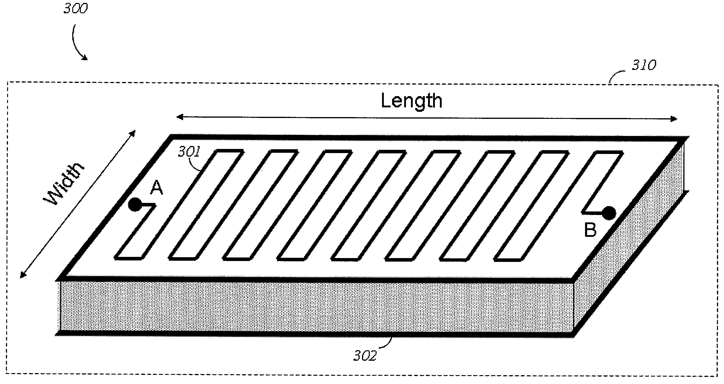
The patent text describes an electrical signal filtering device and an input / output system that use printed circuit boards (PCBs) with conductive traces to connect two components. The device includes a substrate with a continuous circuitous conductive trace (CCT) that connects two points on the substrate. The CCT is made up of a meandering path, a coiling path, or a spiraling path. The PCBs have a first layer with a dissipative metal that is connected to the CCT. The system also includes a first shielding layer and a second shielding layer to reduce interference. The PCBs can be rigid or flexible, and the system can include multiple stages of PCBs to increase the signal path. The technical effects of the invention include improved signal filtering and reduced interference between components.

Problems solved by technology

Maintaining superconducting temperatures may be difficult since many materials that are capable of superconducting do not provide good thermally conductive paths.
Such may be particularly difficult with I / O systems since such I / O systems interface with non-refrigerated environments.

Method used


Image

  • Systems, methods, and apparatus for electrical filters and input/output systems
  • Systems, methods, and apparatus for electrical filters and input/output systems
  • Systems, methods, and apparatus for electrical filters and input/output systems

Examples


Embodiment Construction

[0044]In the following description, certain specific details are set forth in order to provide a thorough understanding of various disclosed embodiments. However, one skilled in the relevant art will recognize that embodiments may be practiced without one or more of these specific details, or with other methods, components, materials, etc. In other instances, well-known structures associated with electrical filters and / or printed-circuit boards have not been shown or described in detail to avoid unnecessarily obscuring descriptions of the embodiments.

[0045]Unless the context requires otherwise, throughout the specification and claims which follow, the word “comprise” and variations thereof, such as, “comprises” and “comprising” are to be construed in an open, inclusive sense, that is as “including, but not limited to.”

[0046]Reference throughout this specification to “one embodiment” or “an embodiment” means that a particular feature, structure or characteristic described in connecti...


PUM


Abstract

An electronic filtering device includes continuous trace on a dielectric substrate and a dissipation layer communicatively coupled to the trace. The dissipation layer may include disconnected metal particles, which may be embedded in a substrate, for example in an epoxy. The continuous trace may be meandering, for example crenulated, coil or spiral signal path. At least a second continuous trace may be spaced from the first by the substrate, and conductively coupled by a via. The electronic filtering device may be used in one or more printed circuit boards (PCBs) that form stages of an input / output system.

Description

CROSS REFERENCE TO RELATED APPLICATIONS[0001]This application claims benefit under 35 U.S.C. 119(e) of U.S. Provisional Patent Application Ser. No. 60 / 981,764, filed Oct. 22, 2007, entitled “Systems, Methods, and Apparatus For Electronic Filters” and U.S. Provisional Patent Application Ser. No. 60 / 988,708, filed Nov. 16, 2007, entitled “Modular Input / Output System and Devices Incorporating Printed Circuit Board Components”, which are incorporated herein by reference in their entirety.BACKGROUNDField [0002]The present systems, methods, and apparatus generally relate to the filtering of electronic signals and particularly relate to modular PCB-based input / output (I / O) systems and devices for use with such I / O systems.Electrical Signal Filtering[0003]During transmission, an electrical signal typically comprises a plurality of components each transmitting at a different frequency. The “filtering” of an electrical signal typically involves the selective removal of certain frequencies fro...

Claims


Application Information

Patent Timeline
Patent Type & Authority Applications(United States)
IPC IPC(8): H03H7/00H10N60/80
CPCH01P1/2039H01P1/227H05K1/0224H05K1/0234H05K2201/09663H05K1/165H05K2201/09263H05K2201/09318H05K1/09
Inventor UCHAYKIN, SERGEY V.
Owner D WAVE SYSTEMS INC
Learn More