Inductor and core thereof

Inactive Publication Date: 2009-04-23
DELTA ELECTRONICS INC
View PDF7 Cites 23 Cited by
  • Summary
  • Abstract
  • Description
  • Claims
  • Application Information

AI Technical Summary

Benefits of technology

[0007]It is an object of the present invention to provide an inductor and core thereof, wherein the magnetic particles

Problems solved by technology

However, the inductor device fabricated by high temperature sintering is difficult in being integrated with integration circuits.
However, agglomeration of the magnetic particle still can't be avoided, thereby resulting in the magnetic particle with a non-uniform aggregate size.
A magnetic particle with aggregate size

Method used


Image

  • Inductor and core thereof
  • Inductor and core thereof
  • Inductor and core thereof

Examples


Embodiment Construction

[0020]The following description is of a mode of carrying out the invention. This description is made for the purpose of illustrating the general principles of the invention and should not be taken in a limiting sense. The scope of the invention is best determined by reference to the appended claims. Wherever possible, the same reference numbers are used in the drawings and the descriptions to refer to the same or like parts.

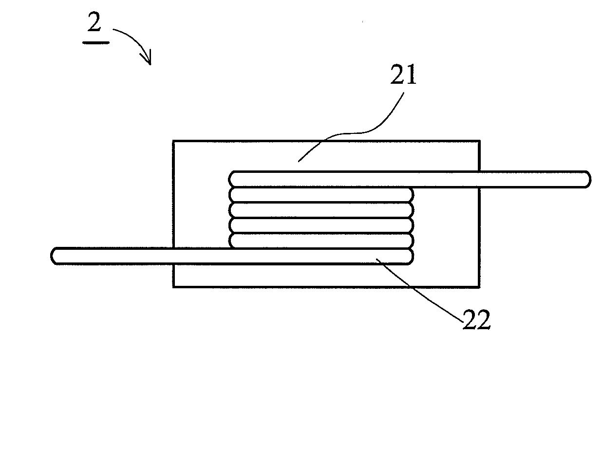
[0021]FIG. 1 shows a sectional view showing an inductor according to a preferred embodiment of the present invention. The inductor 2 of the invention, such as a choke inductor, includes a coil 22 and a core 21. The coil 22 may be a circular-shaped, square-shaped or flat-shaped wire with a plurality of windings. The core 21 covers the coil 22, and the core 21 is formed by mixing a plurality of magnetic particles with resin.

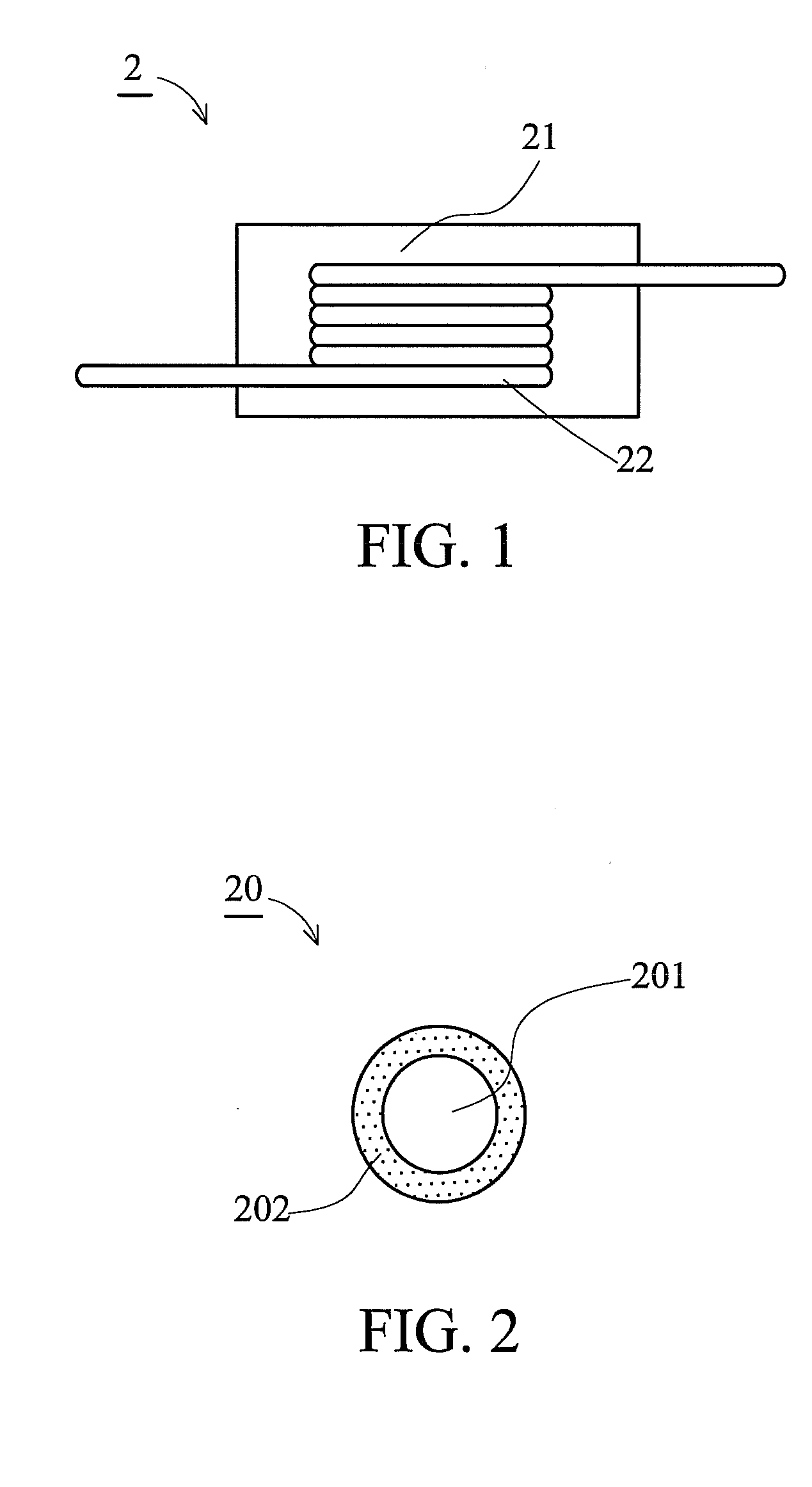
[0022]FIG. 2 shows a sectional view showing a magnetic particle of the present invention. The magnetic particle 20 of the invention includes a ...


PUM


Abstract

An inductor includes a coil and a core. The core covers the coil and includes a plurality of magnetic particles. Each of the magnetic particles includes a nucleus and a first shell enveloping the nucleus. The nucleus and the first shell are formed by different materials with different specific gravities. When the nucleus includes a polymer material, the first shell includes the first magnetic material. When the nucleus includes the first magnetic material, the first shell includes the polymer material.

Description

BACKGROUND OF THE INVENTION[0001]1. Field of the Invention[0002]The invention relates to an inductor and core thereof and particularly relates to an inductor and core thereof with uniformly dispersed magnetic materials and simplified processes.[0003]2. Description of the Related Art[0004]The trend of science and technological development is towards improving electronic device efficiency. The key factor, however, is matching components applied in the electronic device. For example, in the case of a switching power supply, the inductor devices is the key to improving efficiency of the conventional inductor device under high frequency operation.[0005]There are several fabricating methods for inductor devices under high frequency operation. The inductor device can be made of ferrite powders by a high temperature (higher than 800° C.) sintering technique. Alternately, the inductor device can be made of a magnetic particle mixed with a bonding agent with a proper ratio (less than 5 wt %) ...

Claims


Application Information

Patent Timeline
IPC IPC(8): H01F27/255H01F27/02
CPCH01F17/045H01F2017/048H01F2017/046H01F27/255
Inventor LEE, CHENG-CHANGYUAN, ZONG-TINGCHANG, HENG-CHUNGCHEN, HUANG-KUNSHING, TAI-KANG
Owner DELTA ELECTRONICS INC
Why Eureka
Try Eureka