Microchip

Active Publication Date: 2009-04-23
HORIBA LTD
View PDF12 Cites 57 Cited by
  • Summary
  • Abstract
  • Description
  • Claims
  • Application Information

AI Technical Summary

Benefits of technology

[0011]In the case of performing the quantitating operation by the ELISA method with use of a microchip having a fluid circuit in the inside thereof, in order to enable efficient cleaning, it seems to be extremely important that the fluid circuit of the microchip has a structure of being capable of circul

Problems solved by technology

However, by this method, the cleaning liquid is discarded each time the cleaning liquid is let to pass within the beads trap, whereby the measuring apparatus will have a very large scale such as necessitating a cleaning liquid supplying apparatus and an exhaust liquid collecting apparatus on the outside of the microchip, thereby degrading the inherent convenience that the microchip originally has.
However, in this m

Method used


Image

  • Microchip
  • Microchip
  • Microchip

Examples


first embodiment

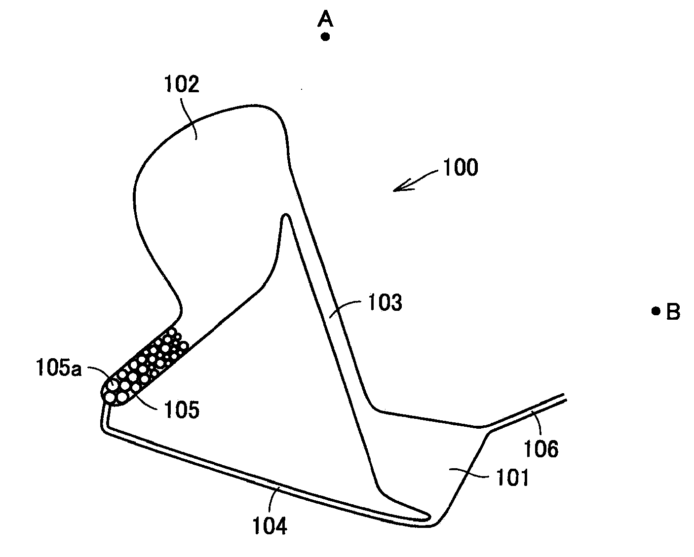
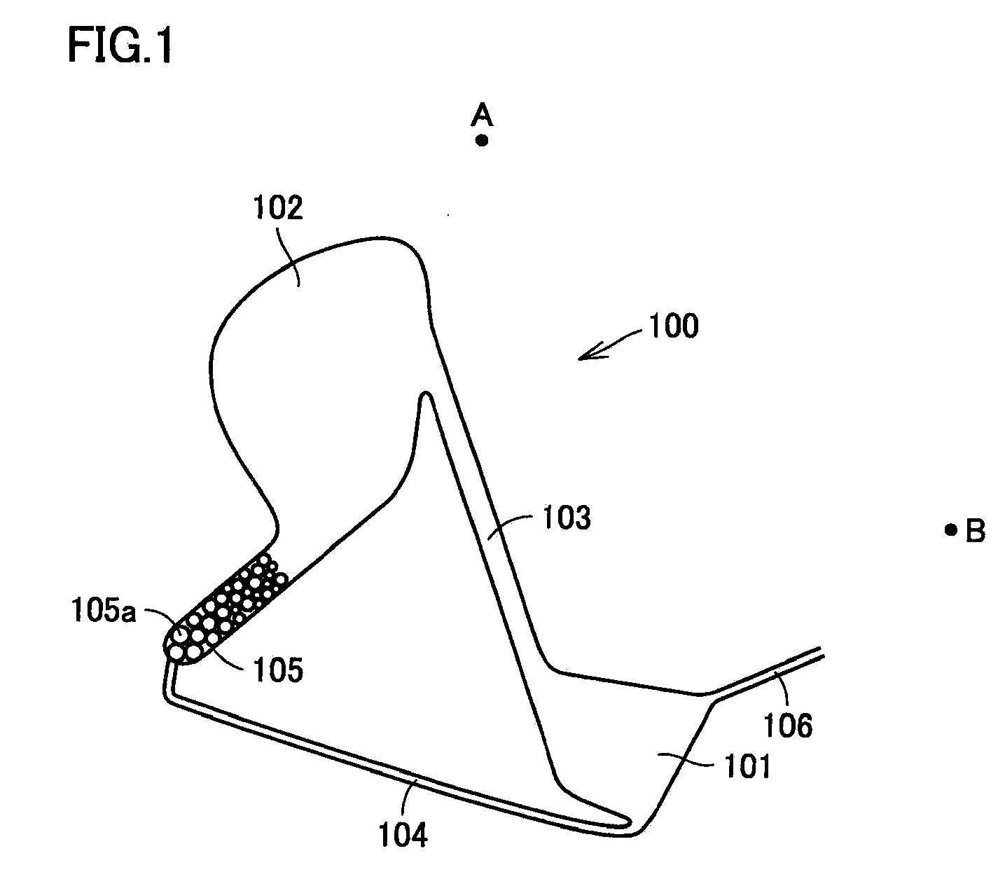
[0026]FIG. 1 is a schematic top view illustrating one example of a principal portion (circular path) of a fluid circuit with which the microchip of a first embodiment is provided. As described above, the microchip of the present invention may have a liquid reagent holding portion, a measuring portion, a reaction (mixing) portion, a detecting portion, and the like. However, for these portions, a conventionally known structure can be applied, so that the illustration thereof is not shown. Also, the principal portion (circular path) shown in FIG. 1 constitutes the fluid circuit of the microchip, and is formed in the inside of the microchip; however, in FIG. 1 (the same applies to the following FIGS. 2 to 6 as well), for providing a more definte description, the internal structure of the microchip is shown by being drawn out. The microchip of the present embodiment can be suitably used as a chip for quantitating an object substance by the ELISA method.

[0027]Here, a microchip having a fl...

second embodiment

[0041]FIGS. 3A and 3B are schematic views illustrating one example of a principal portion (circular path) of the fluid circuit with which the microchip of a second embodiment is provided, where FIG. 3A is a schematic top view thereof, and FIG. 3B is a cross-sectional view along the line IIIB-IIIB in FIG. 3A. The microchip of the present embodiment has a three-layer structure made by laminating a first substrate 310, a second substrate 320, and a third substrate 330. On second substrate 320, there is formed grooves that forms a path having a two-layer structure made of an upper-side path and a lower-side path (see FIG. 3B). The microchip of the present embodiment has a first reservoir 301, a measuring portion 305 disposed adjacent thereto, and a second reservoir 302, where measuring portion 305 and second reservoir 302 are connected by a first path 303. At the upper part of measuring portion 305 (on the side nearer to first reservoir 301), there is formed a third path 306 for dischar...

third embodiment

[0047]FIGS. 5A and 5B are schematic views illustrating one example of a principal portion (circular path) of the fluid circuit with which the microchip of a third embodiment is provided, where FIG. 5A is a schematic top view thereof, and FIG. 5B is a cross-sectional view along the line VB-VB in FIG. 5A. The microchip of the present embodiment has a three-layer structure made by laminating a first substrate 510, a second substrate 520, and a third substrate 530. On second substrate 520, there is formed grooves that forms a path having a two-layer structure made of an upper-side path and a lower-side path (FIG. 5B). In this point, the present embodiment is similar to the above-described second embodiment. The microchip of the present embodiment has a first reservoir 501 and a second reservoir 502, and these are connected by a first path 503 which is an upper-side path. In first reservoir 501, there are formed a third path 506 and a fourth path 507 for introducing or discharging a liqu...


PUM


Abstract

A microchip having a fluid circuit therein for passing a liquid is provided, wherein the fluid circuit has a first reservoir and a second reservoir for storing at least a part of the liquid, a first path connecting the first reservoir and the second reservoir, and a second path connecting the first reservoir and the second reservoir at a position different from the first path, and the first reservoir, the second reservoir, the first path, and the second path constitute a circular path capable of circulating the liquid.

Description

BACKGROUND OF THE INVENTION[0001]1. Field of the Invention[0002]The present invention relates to a microchip useful as a μ-TAS (Micro Total Analysis System) that is suitably used for biochemical testing of DNA, protein, cells, immunity, or blood, chemical synthesis, and environmental analysis, and more particularly to a microchip having a fluid circuit therein.[0003]2. Description of the Related Art[0004]In recent years, in the field of medicine, health, food, drug creation and so on, there is an increasing importance of sensing, detecting, or quantitating a biological substance such as DNA (Deoxyribo Nucleic Acid), an enzyme, an antigen, an antibody, protein, virus, or cells as well as a chemical substance. Therefore, various biochips and microchemical chips (hereafter, these are generally referred to as microchips) are proposed that can conveniently measure these.[0005]Such a microchip can perform a series of experiments and analysis operations that are carried out in experiment l...

Claims


Application Information

Patent Timeline
IPC IPC(8): B04B5/10B01J19/00
CPCB01L3/50273B01L2200/0647B01L2200/10B01L2400/0412B01L2300/0806B01L2300/088B01L2400/0409B01L2300/0627
Inventor MOMOSE, SHUN
Owner HORIBA LTD
Why Eureka
Try Eureka