
Superconductive connection of the end pieces of two superconductors and method for manufacturing this connection

a superconductors and end piece technology, applied in the direction of superconducting magnets/coils, connection contact material, magnetic bodies, etc., can solve the problems of affecting the production of superconducting connections, unable to maintain current operation, and unable to achieve superconducting properties, etc., to achieve high magnetic induction, simple production method, and simple effect of connection

Inactive Publication Date: 2009-04-23
SIEMENS AG
View PDF7 Cites 28 Cited by
  • Summary
  • Abstract
  • Description
  • Claims
  • Application Information

AI Technical Summary

Benefits of technology

[0010]An object of the present invention to provide a connection or a connection device between superconductive conductors at end pieces that enables high magnetic inductions of above 1 Tesla above 2 Tesla without degradation of their current capacity, and, particularly that can be produced in a simple manner. It is also an object to provide a suitable method for simple production of such connections.
[0018]The use of corresponding connections in superconductive magnets enables a persistent current operation in high magnetic fields as is required for, for example, high field magnets in magnetic resonance tomographs.
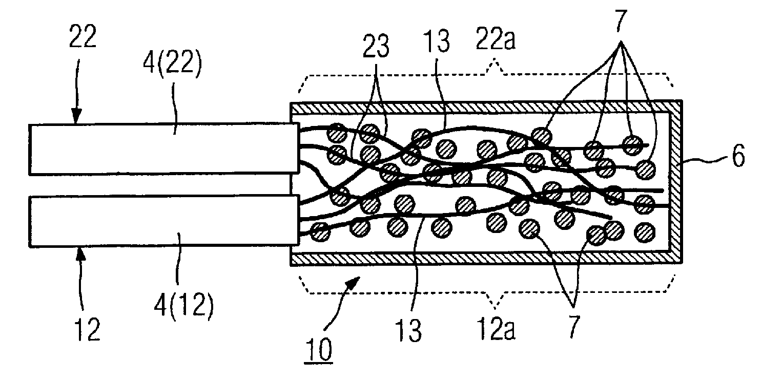
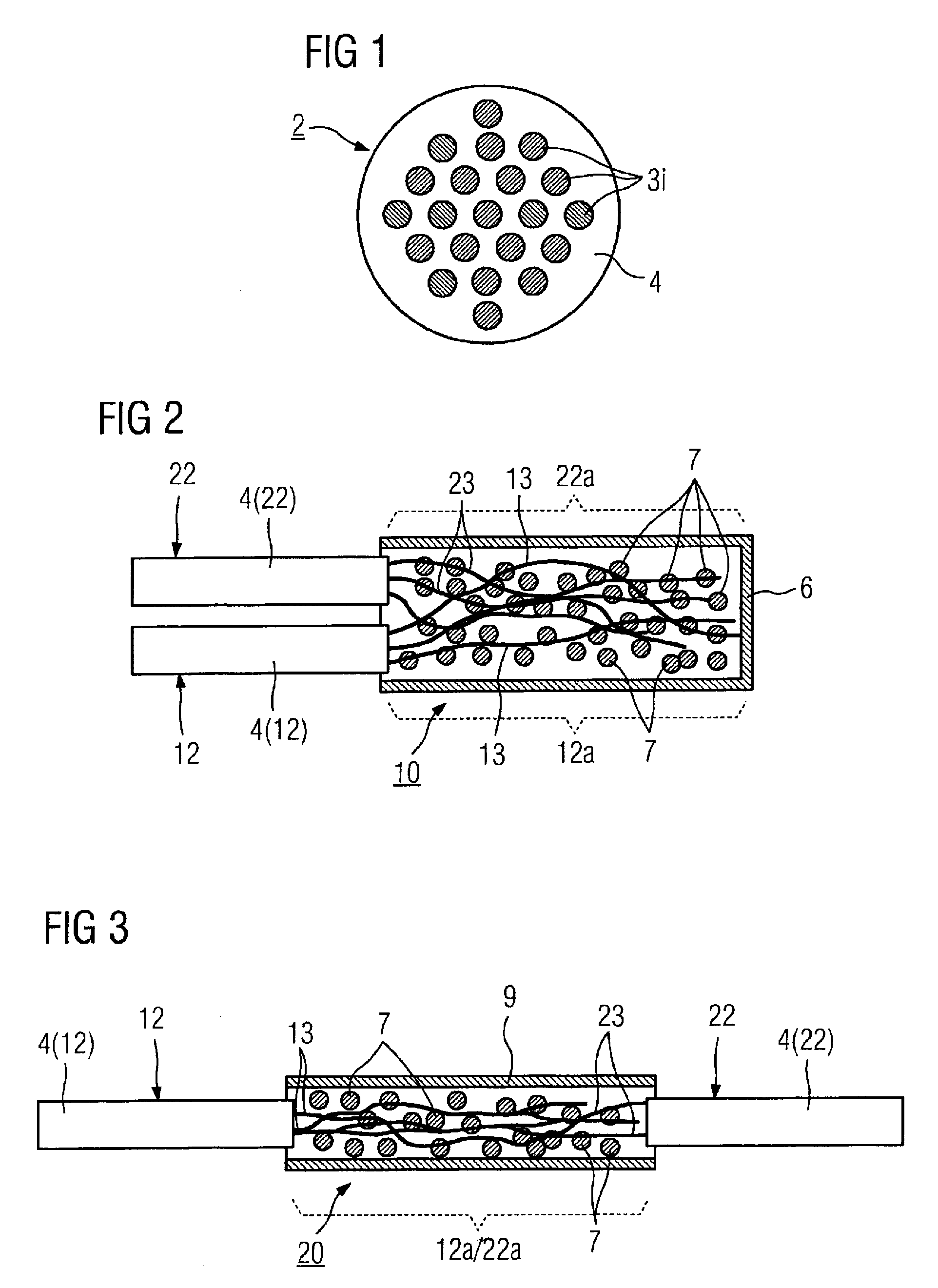
[0025]The above object also is achieved in accordance with the present invention by a method for manufacturing a superconductive connection as described above, including the steps of stripping the superconductive conductor leads at least partially of their matrix material at the end pieces thereof that are to be connected together, inserting the stripped superconductive leads into a sheath or bushing, and additionally inserting MgB2 contact material into the sheath or bushing, and reducing the cross-section of the filled sheath or bushing.
[0026]The method is characterized in particular by its simplicity. The cross-section reduction alone advantageously suffices in many cases in order to achieve the desired connection, which also enables a use under high field conditions.
[0028]The MgB2 contacting material is introduced into the sheath or bushing in powder form. A more compact design with intensive contacting between the superconductive parts and the contacting material can thus be achieved.

Problems solved by technology

However, this makes it necessary that the loop of the magnet winding through which current flows possesses practically no electrical resistance.
However, these superconductive connections react sensitively to magnetic fields.
Namely, if the magnetic field or, respectively, the magnetic induction exceeds a certain limit value (which is typically between 1 Tesla and 2 Tesla), the connection shows an electrical resistance and thus makes a persistent current operation impossible.
Given superconductive high field magnets whose magnetic induction is, for example 3 Tesla or more, this leads to problems since the connections must be attached at points in which the local magnetic field is below the cited limit value.
It can even become impossible given very high fields.
At fields above this critical magnetic field, they lose their superconductive properties and are therefore frequently not suitable for fashioning superconductive high field contacts.
The problem occurs that the filaments do not enter into any large-area contacts, but rather point contacts.
However, the current capacity then decreases further with increasing magnetic field strengths, such that connections of this type are also not suitable for many superconductive high field contacts.
The known method is therefore very complicated and not usable in many cases.

Method used


Image

  • Superconductive connection of the end pieces of two superconductors and method for manufacturing this connection
  • Superconductive connection of the end pieces of two superconductors and method for manufacturing this connection

Examples


Embodiment Construction

[0034]The superconductors in FIG. 1 are of a known type. They can be of the type known as single core (monocore) superconductors or (as shown in FIG. 1) the type known as multi-filament superconductors. Such a superconductor 2 has multiple superconductive conductor leads or filaments 3i that are embedded in a matrix 4 made of normally-conductive material. All known LTC or HTC superconductive materials (for example NbTi, Nb3Sn, MgB2, YBa2Cu3Ox or (Bi,Pb)2Dr2Ca2Cu3Oy) are suitable as material for the conductor leads 3i. Materials known for the matrix are either elementary (for example Cu, Ni, Ag, Fe, Wo, Al) or alloys, in particular of these elements (for example CuNi, AgMg, CuSn, CuZn or NiCr).

[0035]In order to be able to contact at least two end pieces of corresponding multi-filament superconductors or even monocore superconductors with one another according to the invention in a low-resistance manner, with a connection or, respectively, connection device, in the region of the end p...


PUM

PropertyMeasurementUnit
critical temperatureaaaaaaaaaa
temperatureaaaaaaaaaa

Abstract

In a superconductive connection for two end pieces of superconductors that each have a matrix of normally-conductive material and at least one superconductor lead, of superconductive material, in the matrix, and in a method for making such a superconductive connection, the respective end pieces of the conductor leads are stripped of the matrix material and are inserted into a sheath or bushing. MgB2, as superconductive contacting material, is additionally inserted into the sheath or bushing, so as to at least partially fill regions in the sheath or bushing between the conductor leads. The cross-section of the sheath or bushing is then reduced.

Description

BACKGROUND OF THE INVENTION[0001]1. Field of the Invention[0002]The invention concerns a superconductive connection or a superconductive connection device for the end pieces of at least two superconductors that respectively have a matrix composed of normally-conductive material and at least one superconductive lead composed of superconductive material.[0003]2. Description of the Prior Art[0004]DE 34 13 167 A1 discloses a superconductive connection of the above type, wherein in a connection region in a sheath or bushing, the partially stripped conductor leads of the end pieces are arranged in matrix material, and superconductive contact material is provided within the sheath or bushing at least in portions of the regions between the conductor leads.[0005]Superconductors using LTC (Low Tc) superconductive material or HTC (High Tc) superconductive material are produced as, among other things, single-core conductors or multi-filament conductors of limited conductor length. Given a corre...

Claims


Application Information

Patent Timeline
Patent Type & Authority Applications(United States)
IPC IPC(8): H01B12/00H01L39/24H01R43/00H10N60/01H10N60/80
CPCH01L39/02Y10T29/49014H01R4/68H10N60/80
Inventor LEGHISSA, MARTINO
Owner SIEMENS AG
Learn More