Bone fixation tensioning tool and method

a technology of fixing tools and tools, applied in the field of bone fixation tensioning tools and methods, can solve the problems of insufficient purchase, difficulty in using such hooks, paralysis of patients, etc., and achieve the effect of progressively reducing the tension of the ligature and being easily controlled

Active Publication Date: 2009-04-23
ABBOTT LAB INC +1
View PDF68 Cites 83 Cited by
  • Summary
  • Abstract
  • Description
  • Claims
  • Application Information

AI Technical Summary

Benefits of technology

[0015]Embodiments of the disclosed systems and methods can provide the advantage of providing progressive and continuous tensioning of a ligature used in bone fixing procedures.
[0016]Embodiments of the disclosed systems and methods can provide the advantage of allowing ten...

Problems solved by technology

However, using such hooks can be difficult because their use increases the risk that the physician (or other operative) might contact and potentially damage the spinal cord that extends along the center of the spinal canal (which can result in paralysis of the patient).
U...

Method used


Image

  • Bone fixation tensioning tool and method
  • Bone fixation tensioning tool and method
  • Bone fixation tensioning tool and method

Examples


first embodiment

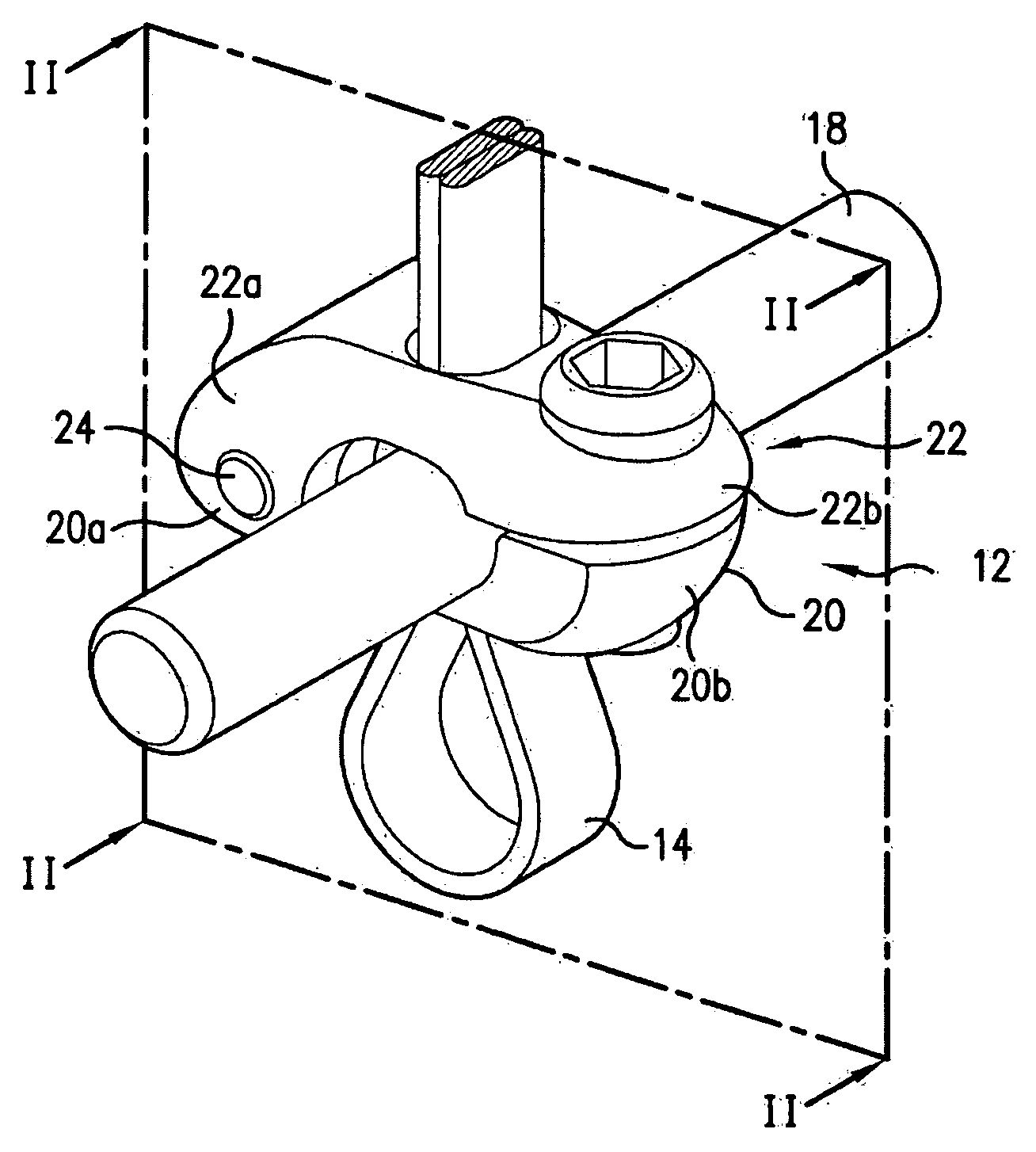
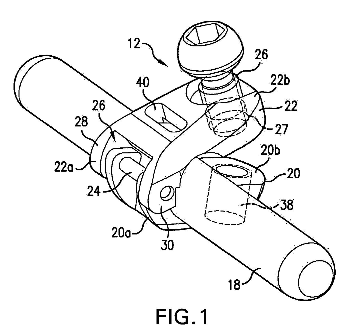
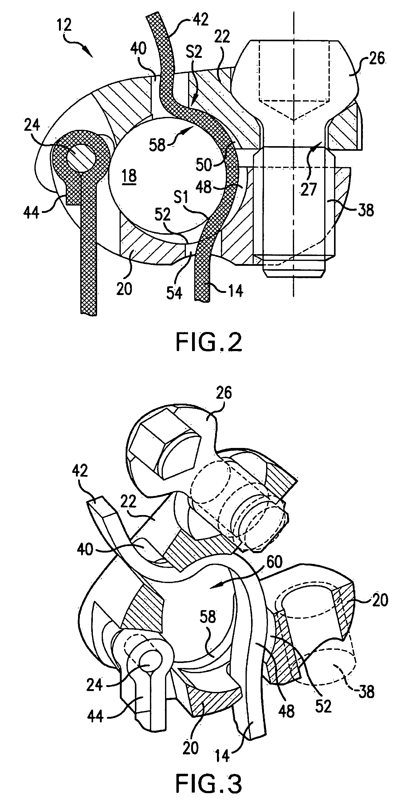
[0074]In some embodiments, flexible ligature 14 may not be ligated around pin 24 or otherwise fixed to connecting part 12. As shown in FIG. 5, in one embodiment, a vertebral fixing system comprises a connecting part 12, a flexible ligature 14, and adjustable locking means 16. The flexible ligature 14 is of elongate shape and is capable of matching the outline of the parts it is to connect together. In this figure, there can also be seen the rod 18 that is to be secured to the vertebra by means of the vertebral fixing system. In the first embodiment, the connecting part 12 is constituted by two longitudinal elements given respective references 22 and 20, each having a first end 22a, 20a and a second end 22b, 20b.

[0075]In FIG. 6A, the longitudinal elements 22 and 20 are hinged to each other at their second ends 22b, 20b about a pivot pin 24.

[0076]In the embodiment described, the locking means are constituted by a screw 26 having a head 26a that is engaged in a bore 28 formed in the f...

second embodiment

[0087]With references to FIGS. 12, 13A, and 13B, there follows a description of two different ways of putting the flexible ligature 14 into place inside the connecting part 12 in the The side wall of the rod 18 and the inside wall of the recess 58 of the part 55 potentially define two passageways 74 and 76 for passing the middle strands of the flexible ligature 14. In the configuration shown in FIG. 13A, only the passageway 74 is used. Thus, both intermediate portions 42 and 44 of the flexible ligature 14 are disposed in the passage 74.

[0088]In the configuration shown in FIG. 13B, the middle portions 42 and 44 of the flexible ligature 14 are disposed respectively one in each of the passageways 74 and 76, i.e. on either side of the rod 18. Advantageously, the free ends of the ligature 14 are accessible for exerting the desired traction in order to obtain suitable clamping on the spinous process prior to locking the clamping ring 62 on the part 55.

[0089]One advantage to this type of ...


PUM


Abstract

A tensioning tool and method for tensioning a conformable ligature of a bone fixing system are disclosed. The ends of a conformable ligature can be passed around bones, bone grafts, tendons, plates, rods, fasteners, or other anatomical or implanted structures, and the like to form a loop. Another portion of the conformable ligature can be coupled to a tensioning tool. The tensioning tool can include a first portion and a second portion in threaded engagement with each other. Rotation of one portion relative to the other can cause tensioning of the conformable ligature through translation of a tensioning member.

Description

TECHNICAL FIELD OF THE DISCLOSURE[0001]This disclosure relates generally to systems and method for fixing bone. In particular, embodiments of the disclosure may be helpful for holding bones, rods, or other structures in a desired configuration or in particular relative position. Even more particularly, the disclosure relates to instruments and methods for installing bone fixing systems.BACKGROUND OF THE DISCLOSURE[0002]The spine is formed of superposed vertebrae, normally aligned along a vertebral axis, from the lumbar vertebrae to the cervical vertebrae, each having a posterior wall from which projects a spinous process and two lateral edges from the walls of which there project ribs and / or transverse processes. If the spine of a person has abnormal curvature, the vertebrae are typically inclined relative to one another and relative to said vertebral axis. The lateral edges of the vertebrae on one side are therefore closer together and form a concave shape while the lateral edges o...

Claims


Application Information

Patent Timeline
IPC IPC(8): A61B17/58
CPCA61B17/7001A61B17/8869A61B17/707A61B17/7053
Inventor BELLIARD, KARL PIERRELARROQUE-LAHITETTE, GILLESDELCLAUD, MARION JEANNE SOPHIEJOUVE, JEAN-LUC ALBERT PAUL
Owner ABBOTT LAB INC
Why Eureka
Try Eureka