Rod Coupling Assembly and Methods for Bone Fixation

a coupling assembly and rod technology, applied in the field of low-profile coupling assembly, can solve the problems of increasing the chance of tissue damage in and around the surgical site during installation, patient discomfort, overtorquing of the locking mechanism,

Inactive Publication Date: 2009-04-23
PIONEER SURGICAL TECH INC
View PDF100 Cites 240 Cited by
  • Summary
  • Abstract
  • Description
  • Claims
  • Application Information

AI Technical Summary

Benefits of technology

[0012]Advantageously, the coupling assembly may be secured to the anchor member after the anchor is secured to the spine, substantially eliminating the need for invasive instruments designed to hold the assembly to the anchor member during implantation and allowing the anchor member to be positioned and secured to the spine without obstruction from the tulip assembly. The coupling assembly may then be provisionally coupled to the anchor member and pivoted to a desired angle before receiving the elongate member. The assembly may also be locked with respect to the anchor member in a fixed orientation relative thereto prior to receipt of the elongate member. Alternatively, the elongate member may be received in the inner tulip member prior to locking of the coupling assembly with respect to the fixation device.
[0013]The insert member and / or outer member may include one or more protrusions, recesses, or other structures to substantially keep the insert member from backing out of the inner space of the outer member once inserted in order to avoid disengagement of the anchor member from the insert member while the assembly is manipulated, for instance to receive the elongate member. The head of the anchor member may also be configured so that it may be shifted to multiple orientations within the insert member, at least one orientation reducing forces that expand the lower portion of the insert member in order to more securely retain the head within the tulip assembly.

Problems solved by technology

Some pedicle screw systems include rather large and bulky assemblies to secure a rod, thus increasing opportunities for tissue damage in and around the surgical site during installation.
Many of these systems also include set-screw type locking mechanisms or multi-part cap structures that require a significant portion of the assembly to be located above the rod, increasing the height or profile of the implants extending radially away from the spinal column, which may cause patient discomfort after implantation.
Systems with set screws also lack a predetermined locking position, often resulting in overtorquing of the locking mechanism.
Many systems also require a rod-receiving device to be coupled to the pedicle screw or other anchor device prior to implantation or include numerous components that must all be carefully assembled together, making these systems more difficult to install and maneuver in a spinal operation where MIS techniques are used.
Furthermore, assemblies with polyaxial fixation devices in the prior art ordinarily rely on downward force of the rod against the head of the fixation device to secure the fixation device against pivoting, so that the assembly, and specifically the rod receiving portion thereof, is provided with little support or stability prior to full locking of the rod.

Method used


Image

  • Rod Coupling Assembly and Methods for Bone Fixation
  • Rod Coupling Assembly and Methods for Bone Fixation
  • Rod Coupling Assembly and Methods for Bone Fixation

Examples


Embodiment Construction

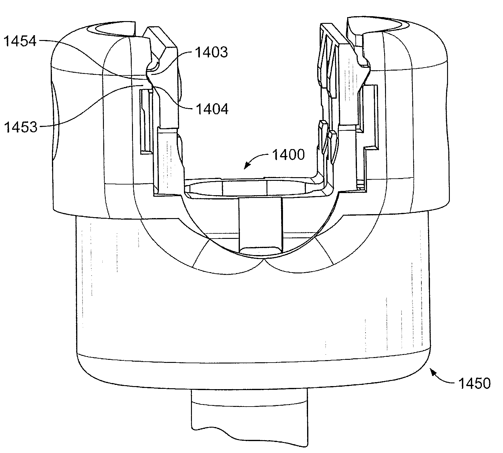
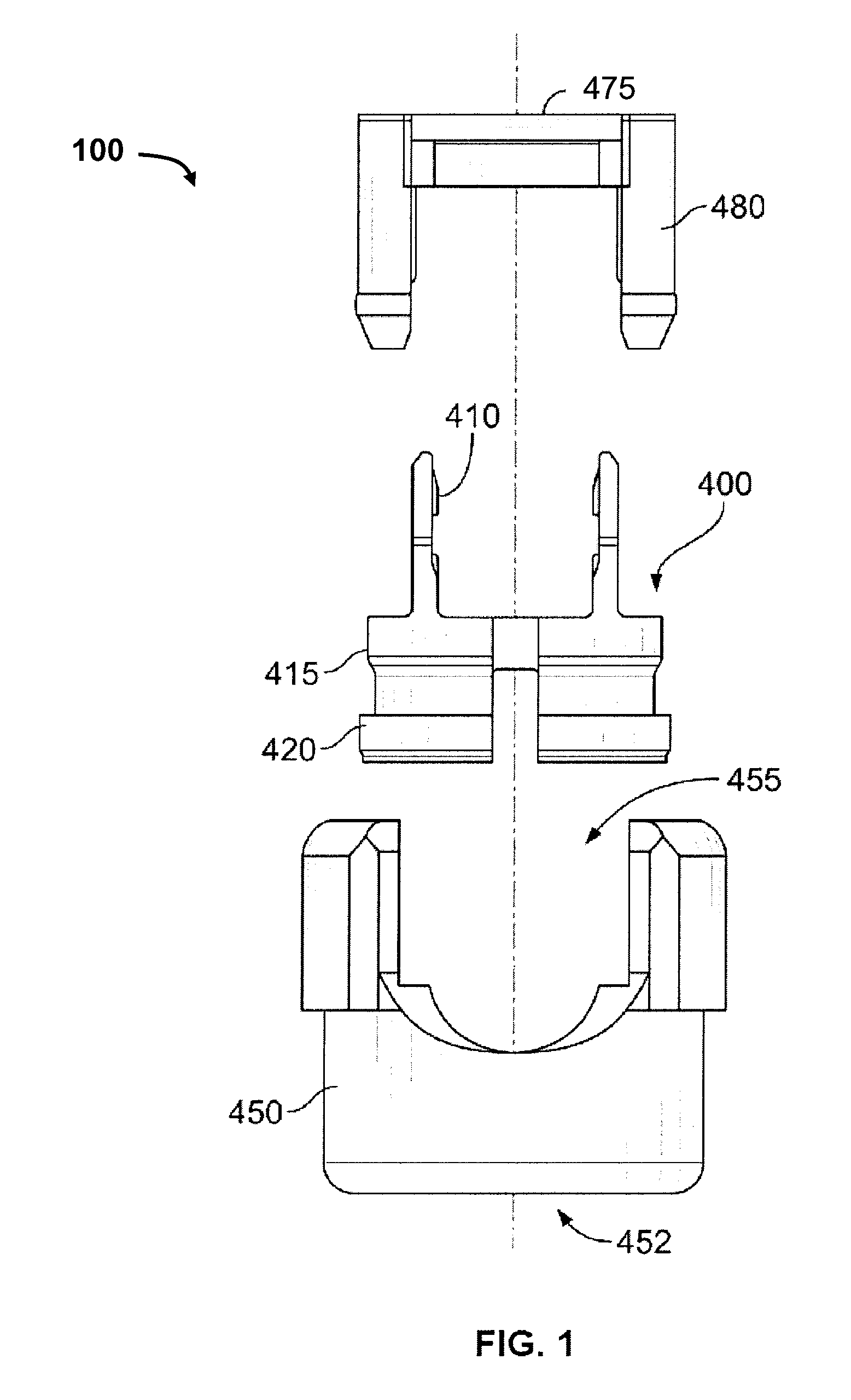
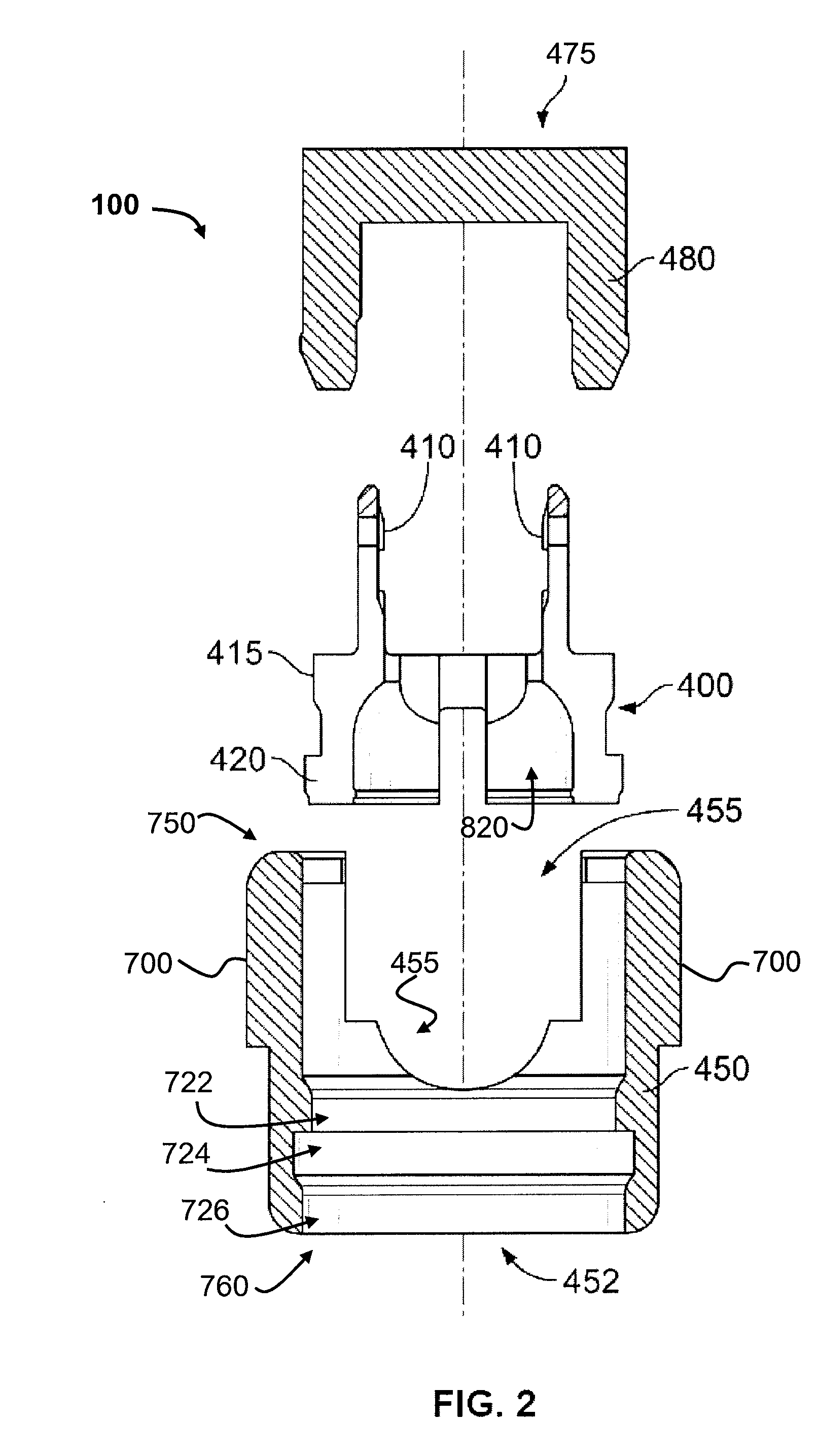
[0028]The present specification describes a system and a method for provisionally and fully locking the orientation of a coupling assembly (preferably a “tulip assembly” in which an insert member is inserted linearly into a space within an outer member) relative to an anchor member or fixation device (e.g. a pedicle screw or hook) and locking the assembly to an elongate member (e.g. a spinal rod) positioned along the spine. Locking may be accomplished by linear or axial movement of the components of the assembly, and may provide for separate locking of the fixation device and rod. Further, according to one exemplary embodiment, the present specification describes the structure of a coupling assembly configured to be placed on the head of a polyaxial pedicle screw after placement of the pedicle screw in a patient's body and configured to receive and positionally secure a top loaded rod. Further details of the present exemplary system and method will be provided below.

[0029]By way of ...


PUM


Abstract

A coupling device for securing an elongate member to the spine is provided. The coupling device comprises a compressible inner member that secures an anchor member therein when the inner member is axially shifted within an outer member. Structures are provided to prevent disassembly of the anchor and coupling device prior to locking of the elongate member.

Description

RELATED APPLICATIONS[0001]This application claims the benefit of U.S. Provisional Application 60 / 981,821, filed Oct. 23, 2007, which is fully incorporated by reference herein.FIELD OF THE INVENTION[0002]The present systems and methods provide for a low profile coupling assembly configured to secure an elongate member or rod to vertebrae. In particular, coupling assemblies having different degrees of locking are provided for receiving and retaining an anchor member and rod, and then fully locking the anchor member and rod against movement relative to the assembly.BACKGROUND OF THE INVENTION[0003]Various devices for internal fixation of bone segments in the human or animal body are known in the art. For instance, pedicle screw and / or hook systems are sometimes used as an adjunct to spinal fusion surgery, and which provides a means of gripping a spinal segment. Such systems may have a rod-receiving portion and an integral anchor portion, or may be provided with a separate anchor member...

Claims


Application Information

Patent Timeline
Patent Type & Authority Applications(United States)
IPC IPC(8): A61B17/04
CPCA61B17/7032A61B17/7049A61B17/7035A61B17/88A61B17/70A61B17/7001A61B17/7037
Inventor BERREVOETS, GREGORYPERROW, SCOTT J.
Owner PIONEER SURGICAL TECH INC
Why Eureka
Try Eureka