Dynamic Spacer Device and Method for Spanning a Space Formed upon Removal of an Intervertebral Disc

Inactive Publication Date: 2009-04-23
SIMPLIFY MEDICAL PTY LTD
View PDF99 Cites 94 Cited by
  • Summary
  • Abstract
  • Description
  • Claims
  • Application Information

AI Technical Summary

Benefits of technology

[0015]In accordance with one aspect of the present invention, a method of spanning a space formed by upon removal of an intervertebral disc includes the steps of: performing a discectomy to remove disc material between two adjacent vertebral bodies; placing an intervertebral spacer between the two adjacent vertebral bodies; and maintaining the disc space between the two adjacent vertebral bodies with the intervertebral spacer without the use of bone graft or bridging bone. The spacer includes two end plates, each end plate having a vertebral body contacting surface and an inner surface, and a connector interconnecting the inner surfaces of the two end plates in a compliant manner which limits motion between the plates to less than a total of 5 degrees of motion in any direction.
[0016]In accordance with another aspect of the invention, an intervertebral spacer for spanning a space formed by upon removal of an intervertebral disc includes two end plates sized and shaped to fit within an intervertebral space and a connector interconnecting the inner surfaces of the two end plates in a compliant manner which limits motion between the plates to less than a total of 5 degrees of motion in any direction. The intervertebral spacer is configured to permanently maintain the disc space between the two adjacent discs without the use of bridging bone.
[0017]In accordance with a further aspect of the invention, a method of spanning a space formed by upon removal of an intervertebral disc includes the steps of: performing a discectomy to remove disc material between two adjacent vertebral bodies; placing an intervertebral spacer between the two adjacent vertebral bodies; and maintaining the disc space between the two adjacent vertebral bodies with the intervertebral spacer within

Problems solved by technology

Back pain takes an enormous toll on the health and productivity of people around the world.
One common cause of back pain is injury, degeneration and/or dysfunction of one or more intervertebral discs.
Discs often become damaged due to wear and tear or acute injury.
Degeneration or other damage to a disc may cause a loss of “disc height,” meaning that the natural space between two vertebrae decreases.
Decreased disc height may cause a disc to bulge, facet loads to increase, two vertebrae to rub together in an unnatural way and/or increased pressure on certain parts of the vertebrae and/or nerve roots, thus causing pain.
In general, chronic and acute damage to intervertebral discs is a common source of back related pain and loss of mobility.
When one or more damaged intervertebral discs cause a patient pain and discomfort, surgery is often required.
However, PEEK is a material that does not allow bone to attach.
Another problem associated with the typical fusion procedure is the subsidence of the cage into the vertebral body.
However, the large amount of open space means that the load on each segment of the cage is sig

Method used


Image

  • Dynamic Spacer Device and Method for Spanning a Space Formed upon Removal of an Intervertebral Disc
  • Dynamic Spacer Device and Method for Spanning a Space Formed upon Removal of an Intervertebral Disc
  • Dynamic Spacer Device and Method for Spanning a Space Formed upon Removal of an Intervertebral Disc

Examples


Embodiment Construction

[0028]Various embodiments of the present invention generally provide for an intervertebral spacer having upper and lower plates connected by a central connector which provides some limited amount of axial compliance or rotational motion between the upper and lower plates. The compliant intervertebral spacer according to the present invention can maintain disc height and prevent subsidence with a large surface area while substantially reducing recovery time by eliminating the need for bridging bone.

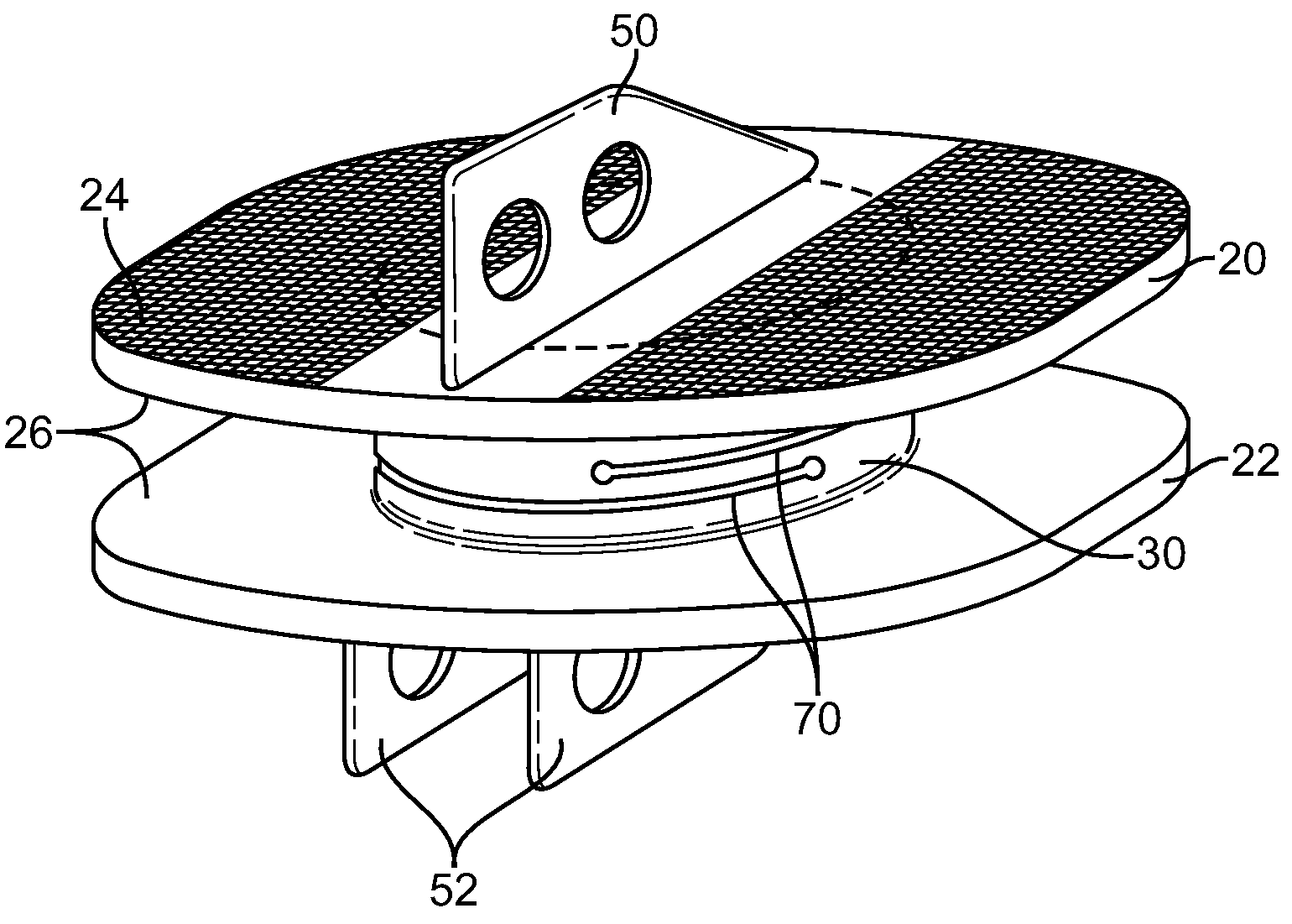
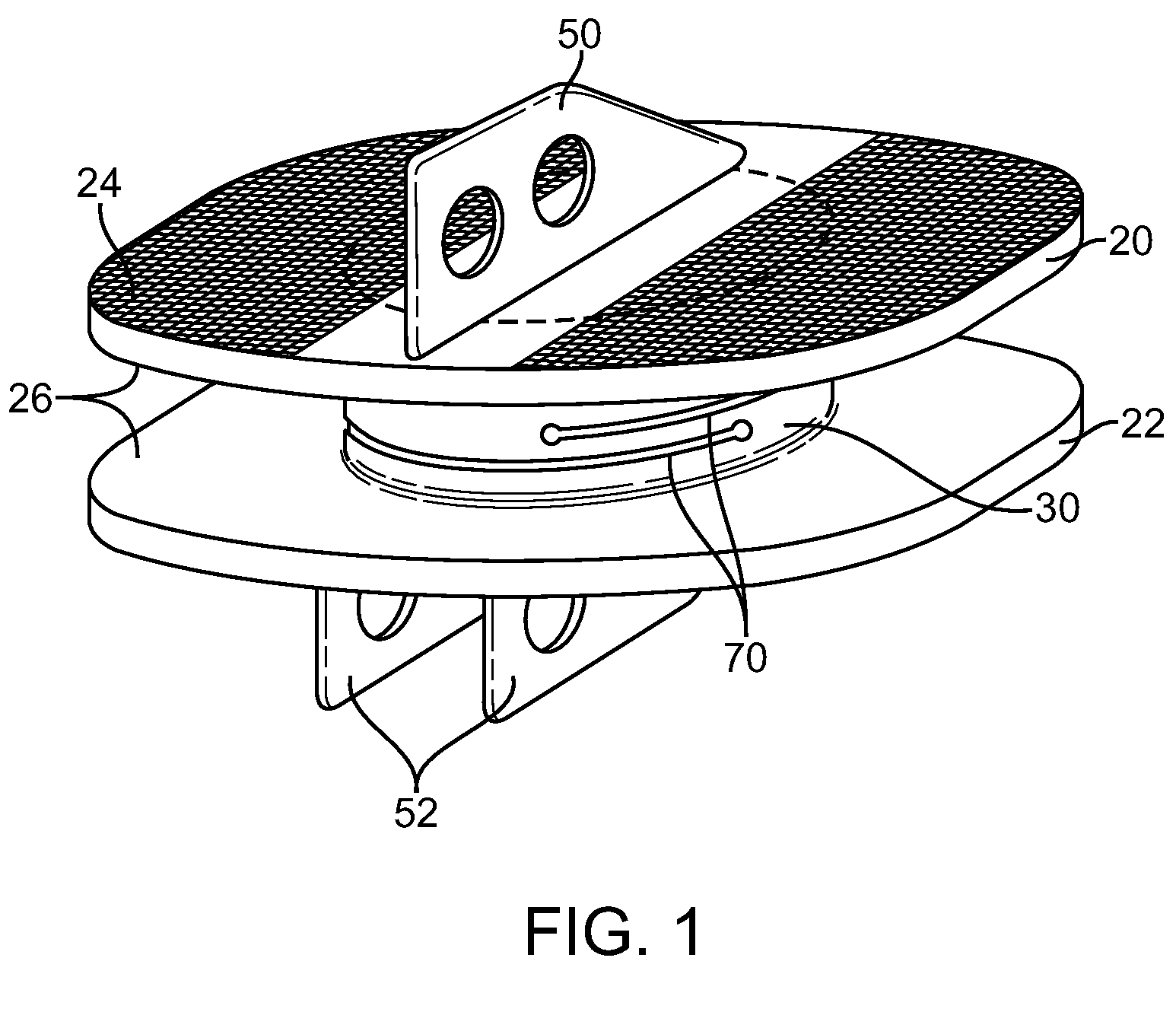
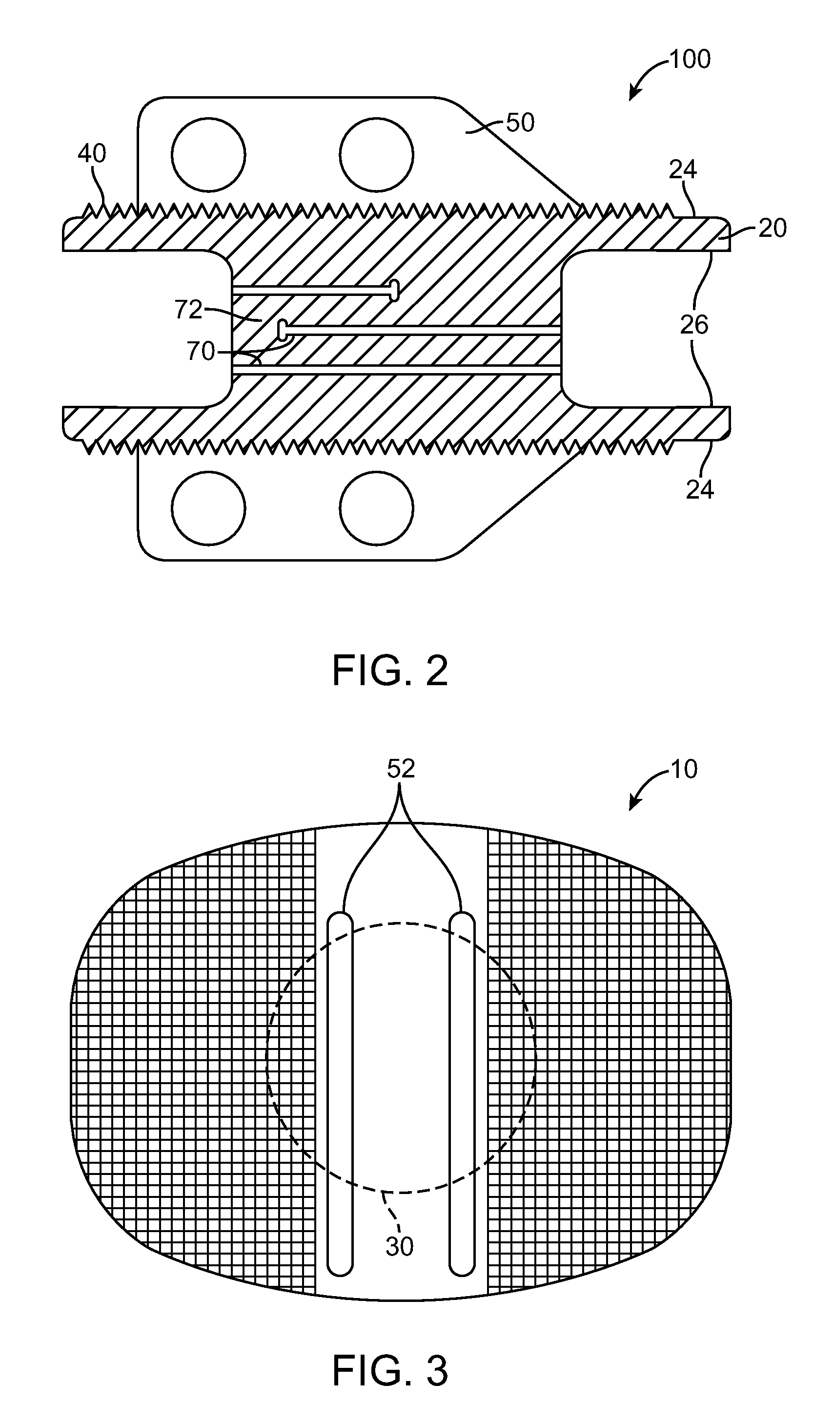
[0029]One example of an intervertebral spacer 10 for maintaining disc height between two adjacent vertebral discs is shown in FIG. 1. The spacer includes two end plates 20, 22, each end plate having a vertebral body contacting surface 24 and an inner surface 26, and a compliant connector 30 interconnecting the inner surfaces of the two end plates. As will be described below some limited rotational and axial motion may be provided between the two plates to reduce loading on the vertebral bo...


PUM

PropertyMeasurementUnit
Lengthaaaaaaaaaa
Fractionaaaaaaaaaa
Fractionaaaaaaaaaa

Abstract

A compliant intervertebral spacer according to the present invention replaces a damage intervertebral disc and functions to maintain disc height and prevent subsidence with a large surface area while substantially reducing patient recovery time. The compliant intervertebral spacer for spanning a space formed by upon removal of an intervertebral disc includes two end plates sized and shaped to fit within an intervertebral space and a compliant connector interconnecting the inner surfaces of the two end plates in a manner which limits motion between the plates to less than a total of 5 degrees of motion in any direction. The intervertebral spacer is configured to permanently maintain the disc space between the two adjacent discs without the use of bridging bone.

Description

CROSS-REFERENCES TO RELATED APPLICATIONS[0001]The present application claims priority from U.S. Provisional Application No. 60 / 981,665 filed Oct. 22, 2007, entitled “Method and Spacer Device for Spanning Space Formed Upon Removal of an Intervertebral Disc,” the full disclosure of which is incorporated herein by reference.BACKGROUND OF THE INVENTION[0002]The present invention relates to medical devices and methods. More specifically, the invention relates to intervertebral spacers and methods of spanning a space formed upon removal of an intervertebral disc.[0003]Back pain takes an enormous toll on the health and productivity of people around the world. According to the American Academy of Orthopedic Surgeons, approximately 80 percent of Americans will experience back pain at some time in their life. In the year 2000, approximately 26 million visits were made to physicians' offices due to back problems in the United States. On any one day, it is estimated that 5% of the working popul...

Claims


Application Information

Patent Timeline
IPC IPC(8): A61F2/44A61B19/00
CPCA61B17/86A61F2310/00976A61F2002/30056A61F2002/30772A61F2002/30787A61F2002/30884A61F2002/30899A61F2002/30904A61F2002/449A61F2250/0032A61F2310/00407A61F2310/00604A61F2310/00796A61F2310/0088A61F2/4465A61F2310/00017A61F2310/00023A61F2310/00029A61F2310/00071A61F2310/00131A61F2310/00179A61F2310/00431A61F2002/30889A61F2/30771
Inventor HOVDA, DAVIDARRAMON, YVESJANSEN, NEVILLEDE VILLIERS, MALAN
Owner SIMPLIFY MEDICAL PTY LTD
Why Eureka
Try Eureka