
Artificial elbow joint

a technology of artificial elbow and elbow joint, which is applied in the field of artificial elbow joint, can solve the problems of inability to obtain sufficient support strength, difficulty in surgery, and inferiority of artificial elbow joint to biological joint, and achieve the effects of reducing the difficulty of surgery, and high skill level

Active Publication Date: 2009-04-23
NAKASHIMA PROPELLER
View PDF4 Cites 34 Cited by
  • Summary
  • Abstract
  • Description
  • Claims
  • Application Information

AI Technical Summary

Benefits of technology

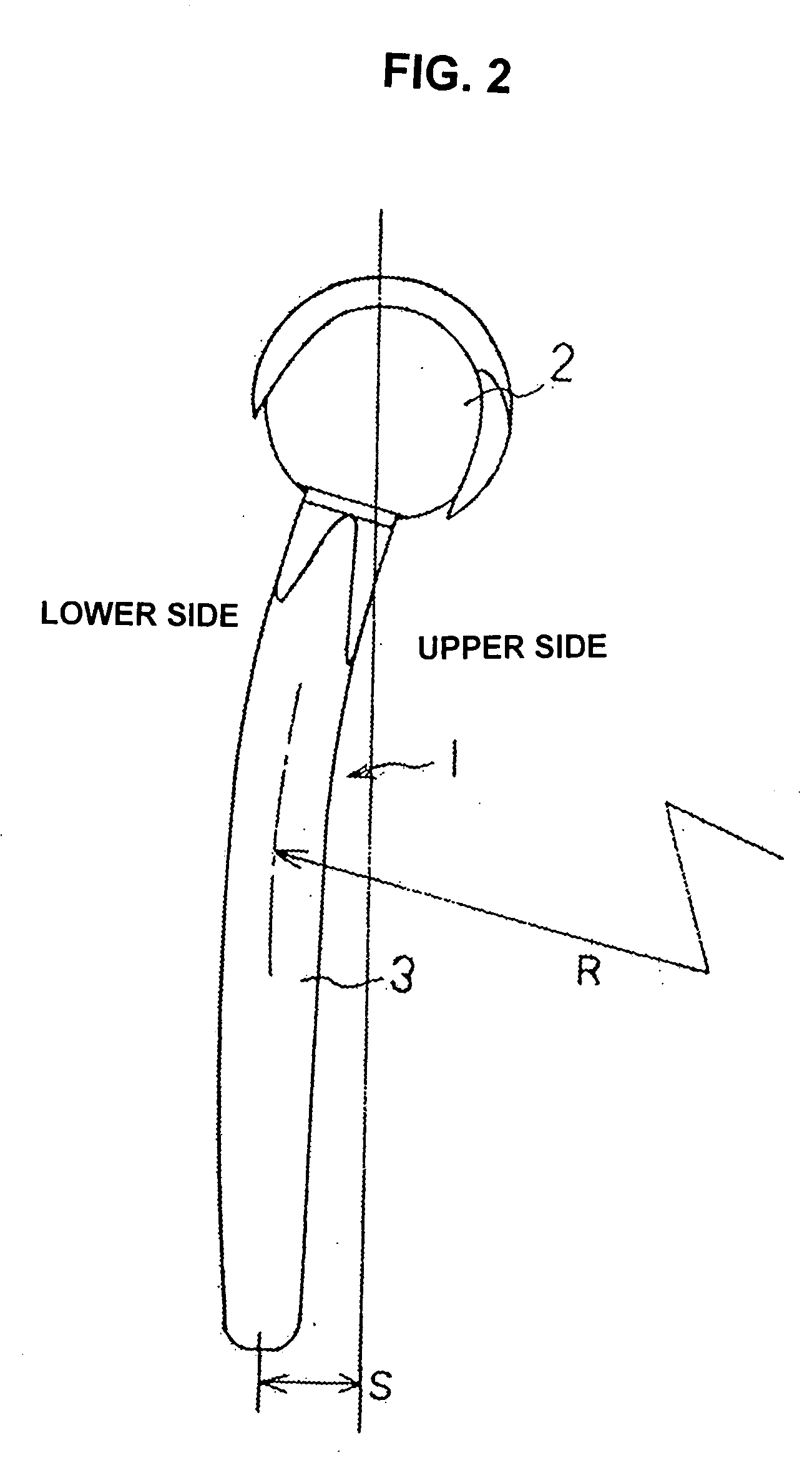
[0010]According the means of claim 1, the humeral component is formed so that the stem thereof follows the lordotic shape of the humeral having no longer an exposed portion; as a result, it has an increased medullary cavity occupation ratio with an intraspinal holding strength. Also, because the trochlea is substantially cylindrical, it needs only be mounted by being imbedded in the epiphysis of the humeral, and no special bone cutting demanding a high level of skill is required. In addition, because the trochlea can turn about the centerline of the stem, it is possible to eliminate the difficulty of being unable to adjust the angle of the trochlea associated with the fact that the attitude wherein the stem of the humeral component is imbedded inside the medullary cavity is specifically determined by the shape

Problems solved by technology

For this reason, the surgery is difficult; and since no rotational function is involved, the artificial elbow joint is functionally inferior to the biological joint.
As a result, the stem of the humeral side component becomes exposed at the olecranon fossa, and sufficient support strength cannot be obtained.
However, in this structure, the bone must be cut to make the distal end to conform to the shape of the concavity, adding difficulty to the surgery, and placing a great deal of burden on the patient.
However, these components are low in strength due to the properties of the material and inferior in terms of support strength, and they also would cause micromotion (which is repetition of minute motions when a force is applied and the component itself deforms), damaging the bone in the periphery of the stem.
As a result, because both the humeral component and the ulnar component have weak support strength, loosening occurs in the course of use, requiring re-surgeries or the like.

Method used


Image

  • Artificial elbow joint
  • Artificial elbow joint
  • Artificial elbow joint

Examples


Embodiment Construction

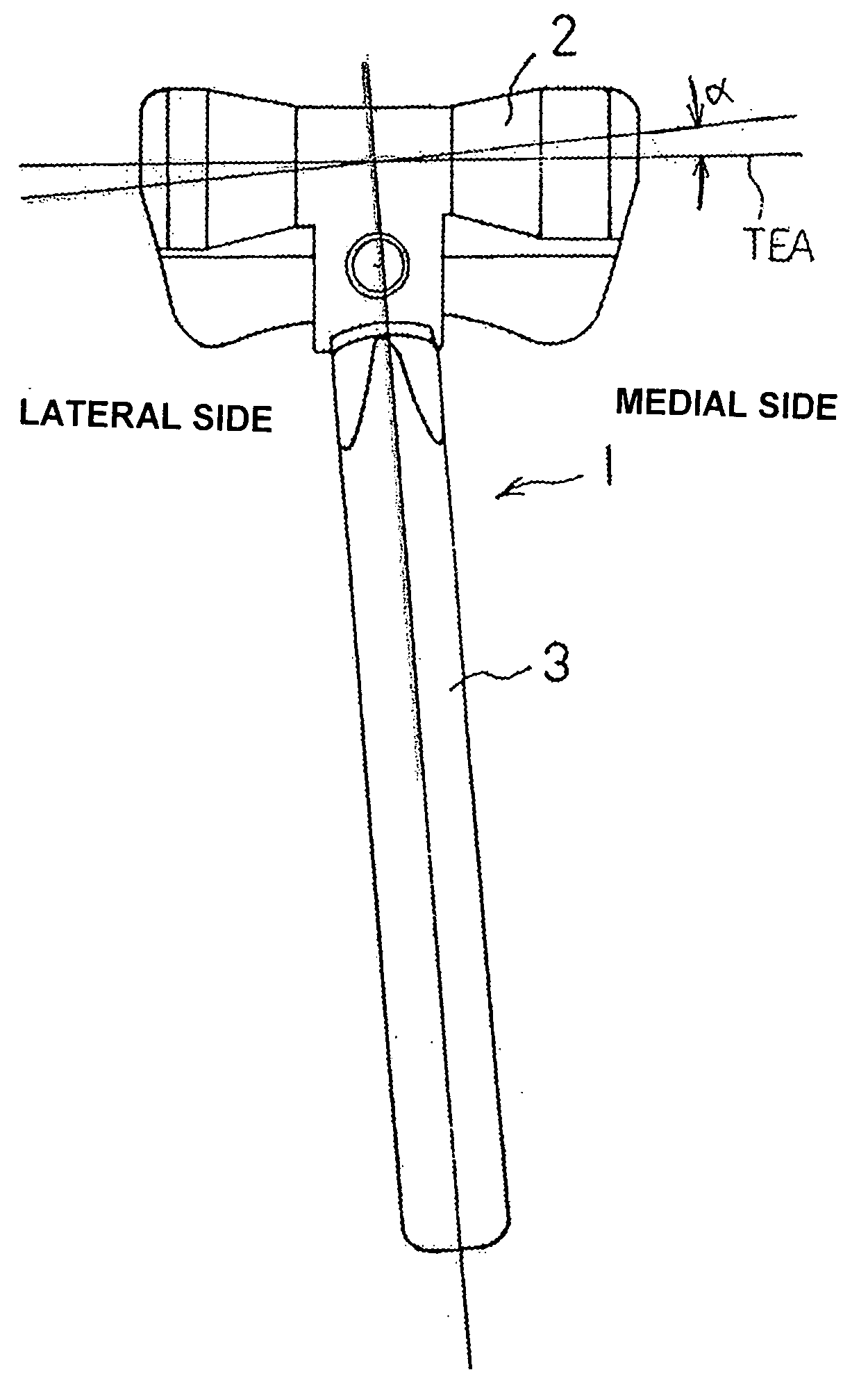
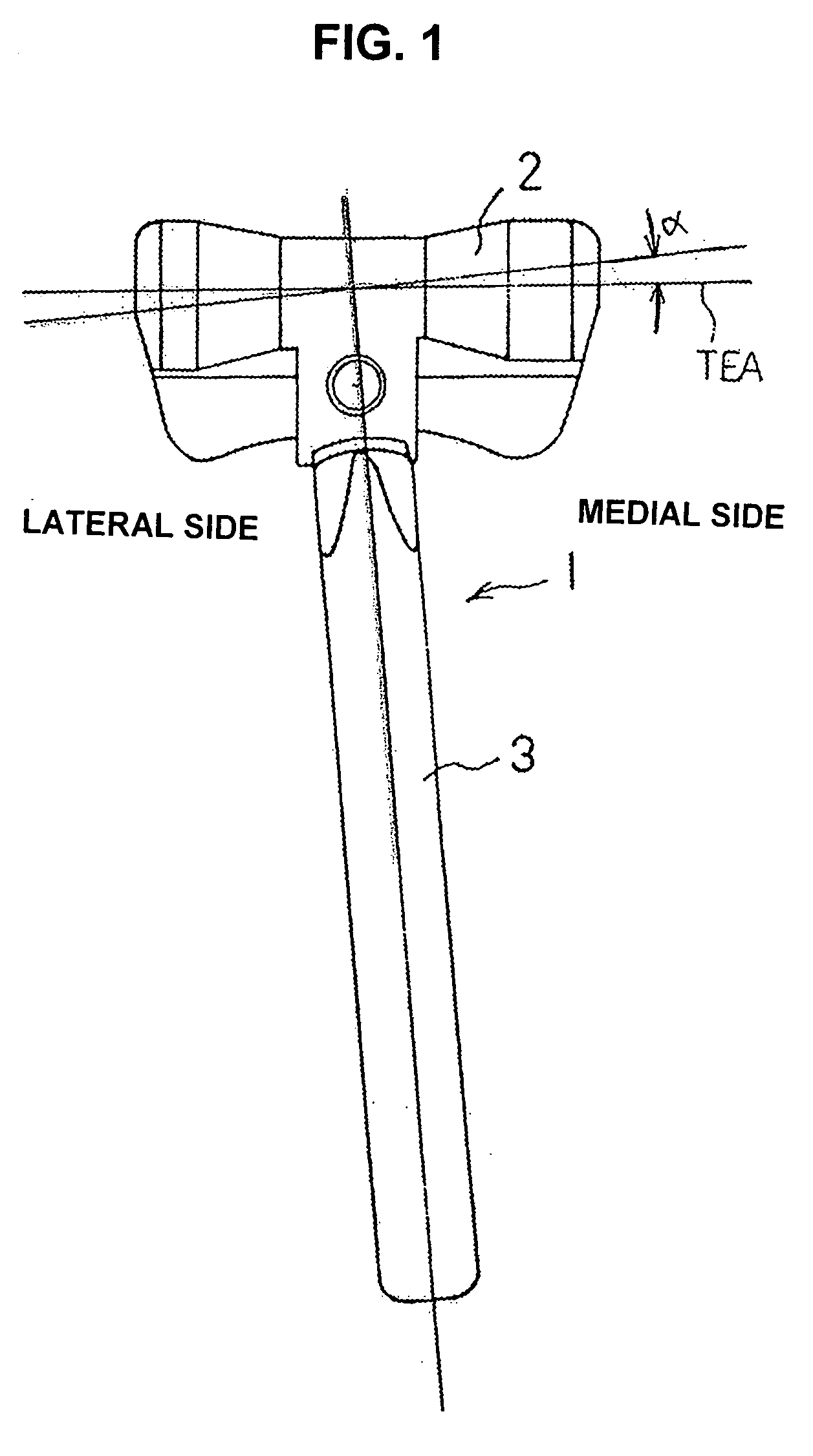
[0041]Embodiments of the present invention will be now described below with reference to the drawings. FIG. 1 is a top plan view of a humeral component 1, while FIG. 2 is a side elevational view thereof. The humeral component 1 is comprised of a trochlea 2 and a stem 3. The trochlea 2 provides a joint function with the joint surface of an ulnar component that will be described subsequently, and it is made either of a metal compatible with the human body, such as a titanium alloy, cobalt chrome molybdenum alloy, or stainless steel alloy or the like, or of a medical ceramic or the like. The trochlea 2 is formed in a substantially cylindrical shape, and its middle portion is in a hollowed-out drum shape like that of the trochlea of a biological elbow joint. The positions and directions referred to in the description below are based on the configuration of the arm in which the humeral and ulna are extended with the palm facing upward.

[0042]The stem 3 of the humeral component 1 is made o...


PUM


Abstract

An artificial elbow joint including a humeral component made of metal and an ulnar component made of resins for replacing an elbow joint. The humeral component of this artificial elbow joint is configured by a substantially cylindrical trochlea and a stem extending from the trochlea that is inserted into the humeral; and the ulnar component is configured by a joint surface member which receives the trochlea of humeral component in a rotatable manner and a stem which extends from the joint surface member and is inserted into the ulna. The stem of the humeral component is curved gently downward overall so as to comply with the lordotic shape of the humeral, and the trochlea is turnable about the centerline of the stem.

Description

TECHNICAL FIELD[0001]This present invention relates to an artificial elbow joint for replacing an elbow joint.BACKGROUND TECHNOLOGY[0002]When the joint function of an elbow joint is lost due to rheumatism, rheumatoid arthritis, external injury or the like, replacement with an artificial elbow joint is performed in the interest of greater quality of life. In such an artificial elbow joint, conventionally, stems of the artificial elbow joint are inserted in the humeral and in the ulna and coupled together with a bendable mechanism in a separable manner as seen in Patent Literature 1. In this artificial elbow joint, the two stems must be inserted at the same time into the humeral and ulna. For this reason, the surgery is difficult; and since no rotational function is involved, the artificial elbow joint is functionally inferior to the biological joint.[0003]In view of the above, such an artificial elbow joint as seen in Patent Literature 2 is proposed. In this artificial elbow joint, a...

Claims


Application Information

Patent Timeline
IPC IPC(8): A61F2/38
CPCA61F2002/3813A61F2/3804
Inventor IKEGAMI, HIROYASUHORIUCHI, YUKIOTAKAYAMA, SHINICHIROMOMOHARA, SHIGEKISEKI, ATSUHITONAKAMURA, TOSHIYASUTANJI, ATSUSHIYAMAMOTO, KEITARO
Owner NAKASHIMA PROPELLER
Learn More