Control system, control method, and robot apparatus

a robot and control system technology, applied in the direction of electric programme control, program control, instruments, etc., can solve the problems of difficult to react to an environment, low updating rate, unsuitable for responding to external forces, etc., and achieve excellent control system and control method

Active Publication Date: 2009-04-23
SONY CORP
View PDF13 Cites 51 Cited by
  • Summary
  • Abstract
  • Description
  • Claims
  • Application Information

AI Technical Summary

Benefits of technology

[0016]It is desirable to provide excellent control system and control method for a link structure constructed by connecting a plurality of rigid bodies, and a robot apparatus.

Problems solved by technology

However, this control method has a problem in that updating rate is low because not only the precision of the cameras is required, but the amount of operation when the peripheral environment shape is reproduced on the basis of measurement results increases.
Further, since this control method is based on positional control, it is considered that it is difficult to reactively adapt to an environment.
The positional control is commonly called “hard control” because its basic purpose is to hold a position, and is not suitable for responding to an external force flexibly or for precisely performing the control of velocity or acceleration.
For example, robot apparatuses which execute a task while performing physical interaction with various outsides originally have low compatibility with the positional control.
However, it is technically difficult to arrange force sensors so that the sensors can detect forces acting on a robot body without omission, and as a result, it is considered that parts where contact with an environment is not permitted may be generated.
Thus, there is a problem in that, unless this main attribute is properly handled, an error may be caused, and vibration may be excited.

Method used


Image

  • Control system, control method, and robot apparatus
  • Control system, control method, and robot apparatus
  • Control system, control method, and robot apparatus

Examples


Embodiment Construction

[0044]Hereinafter, embodiments of the present invention will be described in detail with reference to the drawings.

[0045]The present invention relates to a control system of a link structure constructed by connecting a plurality of rigid bodies. An example of the link structure referred to here is a humanoid robot.

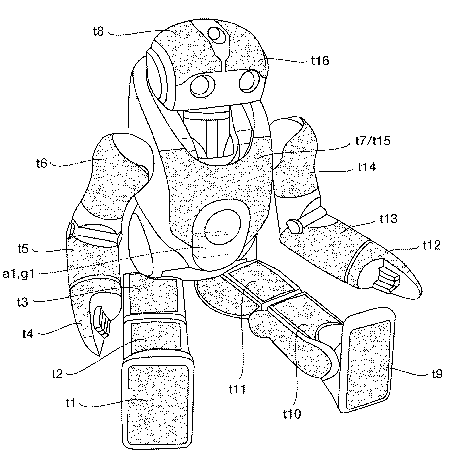
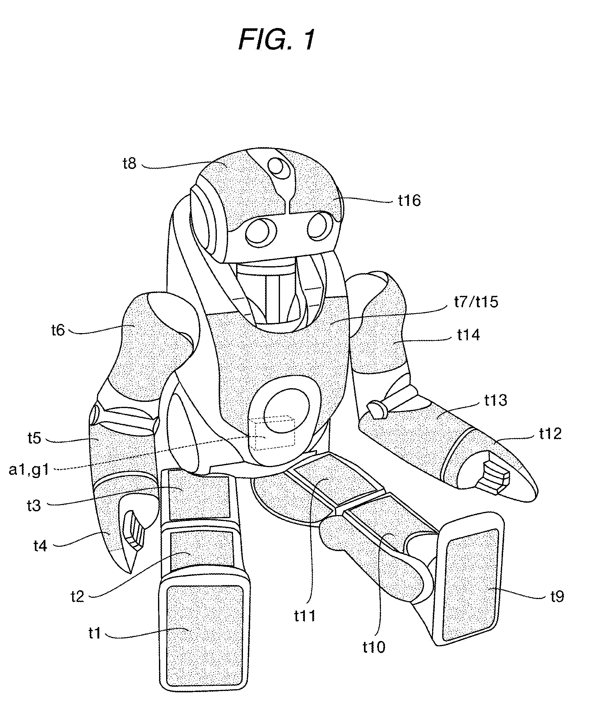
[0046]The external construction of the humanoid robot to which the present invention can be applied is shown in FIG. 1. In the humanoid robot shown, an upper body is connected to a pelvic part via two leg bodies as a moving means, and a waist joint. Two arm parts are connected to the upper body, and a head part is connected to the upper body via a neck joint.

[0047]The right and left leg bodies are provided with a total of six degrees of freedom including three degrees of freedom of a hip joint, one degree of freedom of a knee joint, and two degrees of freedom of an ankle joint, respectively. Further, the right and left arm parts are provided with a total of six degrees of ...


PUM


Abstract

There is provided a control system which controls a link structure constructed by connecting a plurality of rigid body links and driven by making a joint actuator generate an actuator force. The control system includes a mechanical model including geometric parameters and dynamical parameters of the link structure, a virtual external force calculating means for calculating a virtual force acting on the mechanical model of the link structure, a contact part detecting means for detecting contact parts between the link structure and the outside, and an actual force converting means for converting the virtual force calculated by the virtual external force calculating means into an external force capable of existing actually and the actuator force of the joint actuator, using contact information detected by the contact part detecting means. The joint actuator is made to generate the actuator force output by the actual force converting means.

Description

CROSS REFERENCES TO RELATED APPLICATIONS[0001]The present invention contains subject matter related to Japanese Patent Application JP 2007-272099 filed in the Japanese Patent Office on Oct. 19, 2007, the entire contents of which being incorporated herein by reference.BACKGROUND OF THE INVENTION[0002]1. Field of the Invention[0003]The present invention relates to a control system and a control method for a link structure which is constructed by connecting a plurality of rigid bodies, and a robot apparatus, and particularly, to a control system, a control method, and a robot apparatus which sense an unknown environment and obtain a proper external force from surrounding environments which vary every moment, thereby properly adjusting the generating forces of actuators so that a desired task may be achieved.[0004]More specifically, the present invention relates to a control system, a control method, and a robot apparatus which perform not only the precision of positions or postures but...

Claims


Application Information

Patent Timeline
Patent Type & Authority Applications(United States)
IPC IPC(8): B25J13/00
CPCB25J13/084
Inventor NAGASAKA, KENICHIRO
Owner SONY CORP
Why Eureka
Try Eureka