Safety caps for foundation rebar, stakes and anchor bolts and methods of use

a safety cap and anchor bolt technology, applied in the direction of engineering safety devices, mechanical equipment, building components, etc., can solve the problems of tripping and impalement hazards, requiring days or even weeks to assemble before, and large rebar frames

Inactive Publication Date: 2009-04-30
BEERY JOSH
View PDF14 Cites 21 Cited by
  • Summary
  • Abstract
  • Description
  • Claims
  • Application Information

AI Technical Summary

Benefits of technology

[0012]The present invention provides safety caps and related methods of use that may be employed with a variety of rebar, studs, anchor bolts and/or framing stakes commonly used in the construction industry having different sizes, dimensions and/or shapes. The safety caps of the present invention include a collar that fits around a rebar, stud, anchor bolt or framing stake, an upper surface that covers the t...

Problems solved by technology

However, it is common for such rebar frames to be very large, taking days or even weeks to assemble before any concrete is poured.
During this time, the ends of individual bars often protrude outward where they can be a tripping or impalement hazard to workers on the job site.
Then, even after the concrete is poured, in many situations some rebar or studs may still protrude outward from the concrete, posing the same tripping and impalement hazard.
Unfortunately, exposed rebar, studs, anchor bolts and/or framing stakes give rise to numerous safety concerns and can lead to construction site injuries.
It is common for only a short portion of an anchor bolt to protrude up from the foundation, although these portions may be lengthy depending on the requirements of the particular building.
The exposed rebar, studs, anchor bolts and/or framing stakes become tripping hazards at the construction site, and also pose a risk of impalement to any individual who may h...

Method used


Image

  • Safety caps for foundation rebar, stakes and anchor bolts and methods of use
  • Safety caps for foundation rebar, stakes and anchor bolts and methods of use
  • Safety caps for foundation rebar, stakes and anchor bolts and methods of use

Examples


Embodiment Construction

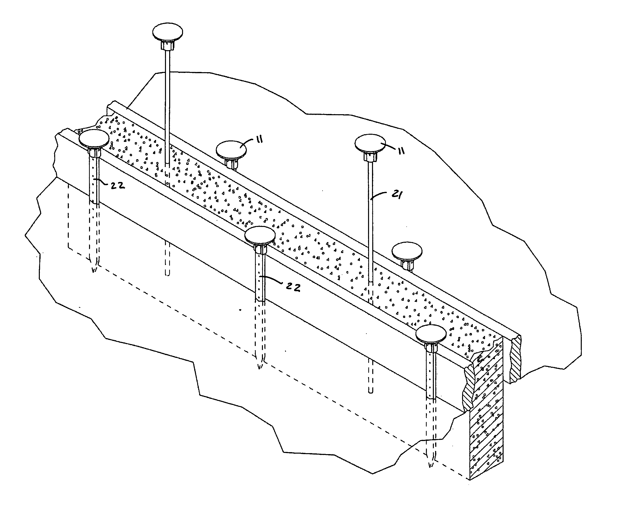
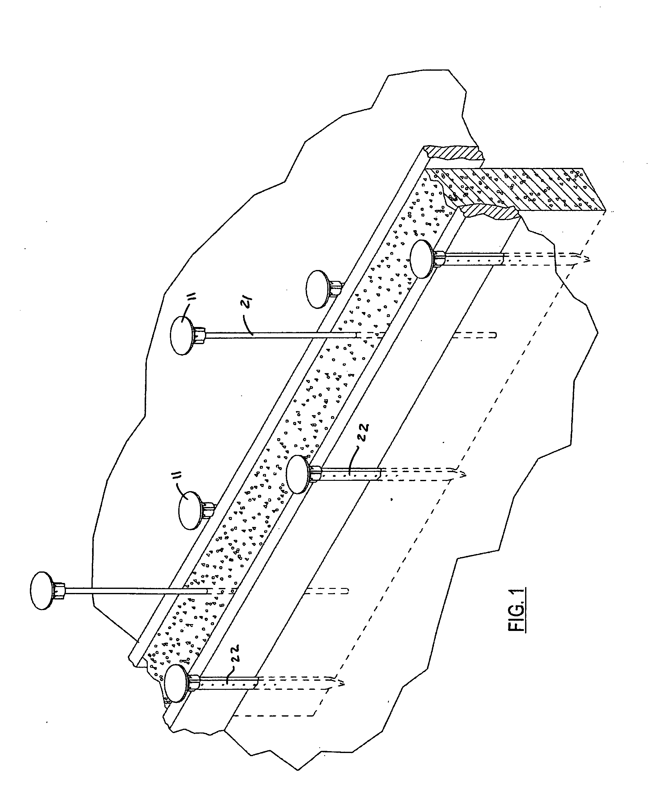
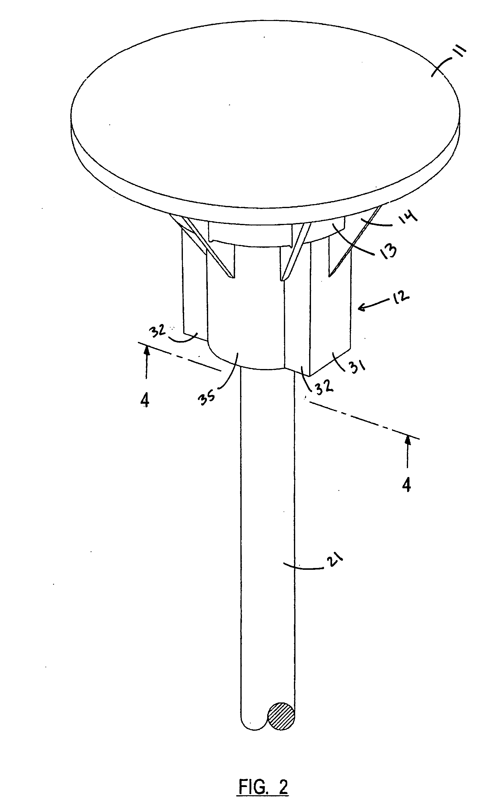
[0032]Referring to the exemplary embodiments of the drawings wherein like reference characters designate like or corresponding parts throughout the several views, and referring particularly to FIGS. 1 through 3, it is seen that the present invention includes a top portion or cap 11 that is attached to a specially shaped collar 12 having a hollow interior. In some embodiments, a reinforcing ring 13 may be provided underneath cap 11, and reinforcing ribs 14 may be provided between cap 11 and collar 12. In the illustrated embodiments, cap 11 is provided in the form of a disk, although it may have other shapes (such as a dome). Cap 11 may also be reinforced with an under plate 15 made of metal or other sturdy rigid material. The support structures 13, 14 and 15 help strengthen the invention in the event that someone falls onto it while it is attached to an anchor bolt 21 or stake 22.

[0033]Collar 12 is hollow, and is shaped so that it may receive a rod or shaft having a symmetrical and / o...


PUM


Abstract

The present invention is a safety cap that may be used with exposed construction rebar, studs, anchor bolts, stakes or shafts of various sizes and shapes to minimize potential impalement injuries suffered by any individual falling upon the exposed shaft. The invention includes a specially shaped collar for receiving differently sized shafts so that the same device may be used on a variety of different shafts. The collar includes inwardly extending deformable flanges that temporarily but securely attach the safety cap to the shaft. Embodiments of the invention may be brightly colored for visibility and reinforced to insure that the invention does not deform or break when downward pressure is asserted upon it.

Description

BACKGROUND OF THE INVENTION[0001]1. Field of the Invention[0002]The present invention relates to safety devices for the construction industry, and more particularly to new and improved safety caps for use in building construction where rebar, studs, flat or round stakes and / or anchor bolts of varying sizes and shapes are used or installed, and related methods of use.[0003]2. Description of the Prior Art[0004]Metal reinforcement bars (rebar) are commonly used in concrete construction to provide added stability to concrete structures. In typical construction, a frame or web of metal reinforcement bars is typically constructed, and then concrete is poured around and over the frame. This provides internal strength and stability to the frame. However, it is common for such rebar frames to be very large, taking days or even weeks to assemble before any concrete is poured. During this time, the ends of individual bars often protrude outward where they can be a tripping or impalement hazard...

Claims


Application Information

Patent Timeline
IPC IPC(8): F16P1/00
CPCE04C5/161F16P1/00E04G21/32E04G21/3252
Inventor BEERY, JOSH
Owner BEERY JOSH
Why Eureka
Try Eureka