Automatic control system for a header of an agricultural harvesting machine and method of operation of the same

a harvesting machine and automatic control technology, applied in the direction of picking devices, agricultural tools and machines, picking devices, etc., can solve the problems of falling of the reel drive and/or the sickle drive, affecting the operation of the harvesting machine, and the possibility of raising all or part of the cutter bar as a result of contacting the ground, etc., to achieve the effect of small up and down movements

Inactive Publication Date: 2009-04-30
CNH IND AMERICA LLC
View PDF20 Cites 56 Cited by
  • Summary
  • Abstract
  • Description
  • Claims
  • Application Information

AI Technical Summary

Benefits of technology

[0017]As an advantage of the invention, for smaller up and down movements of the cutter bar, for instance, resulting from the cutter bar floating over normal irregularities of the ground, the control system can output reel position commands to move the reel, to maintain the desired relation to the cutter bar. Then, when the cutter bar movements are greater, such as can be expected for abrupt changes in ground contour, e.g., swails and the like the system will raise the header, such that the cutter bar will ...

Problems solved by technology

Observed problems that can occur include that if the tines of the reel are too close to the cutter bar, the sickle can cut the tines if of a soft material such as plastic, and can damage the knife edges of the sickle and cause slippage of the reel drive and/or the sickle drive if the tines are of a harder material such as metal.
This can occur unexpectedly.
With the lengthening of the headers, for instance, to lengths of 40 feet and greater, when in the float mode, the possibility of the raising all or part of the cutter bar as a result of contacting the ground is increased, due for instance, to unevenness of the ground.
Also, because of the greater header width, it can be harder for a combine operator to detec...

Method used


Image

  • Automatic control system for a header of an agricultural harvesting machine and method of operation of the same
  • Automatic control system for a header of an agricultural harvesting machine and method of operation of the same
  • Automatic control system for a header of an agricultural harvesting machine and method of operation of the same

Examples


Embodiment Construction

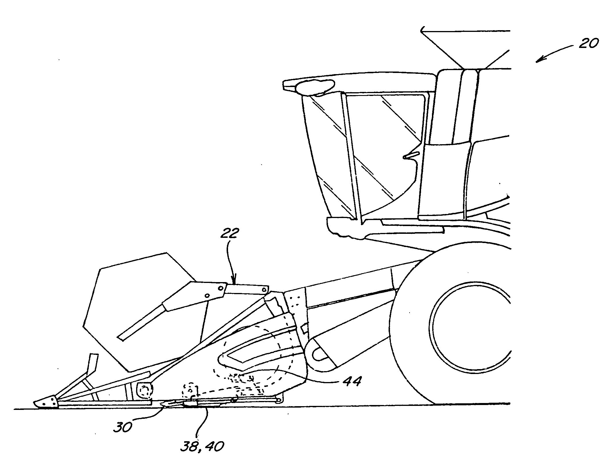
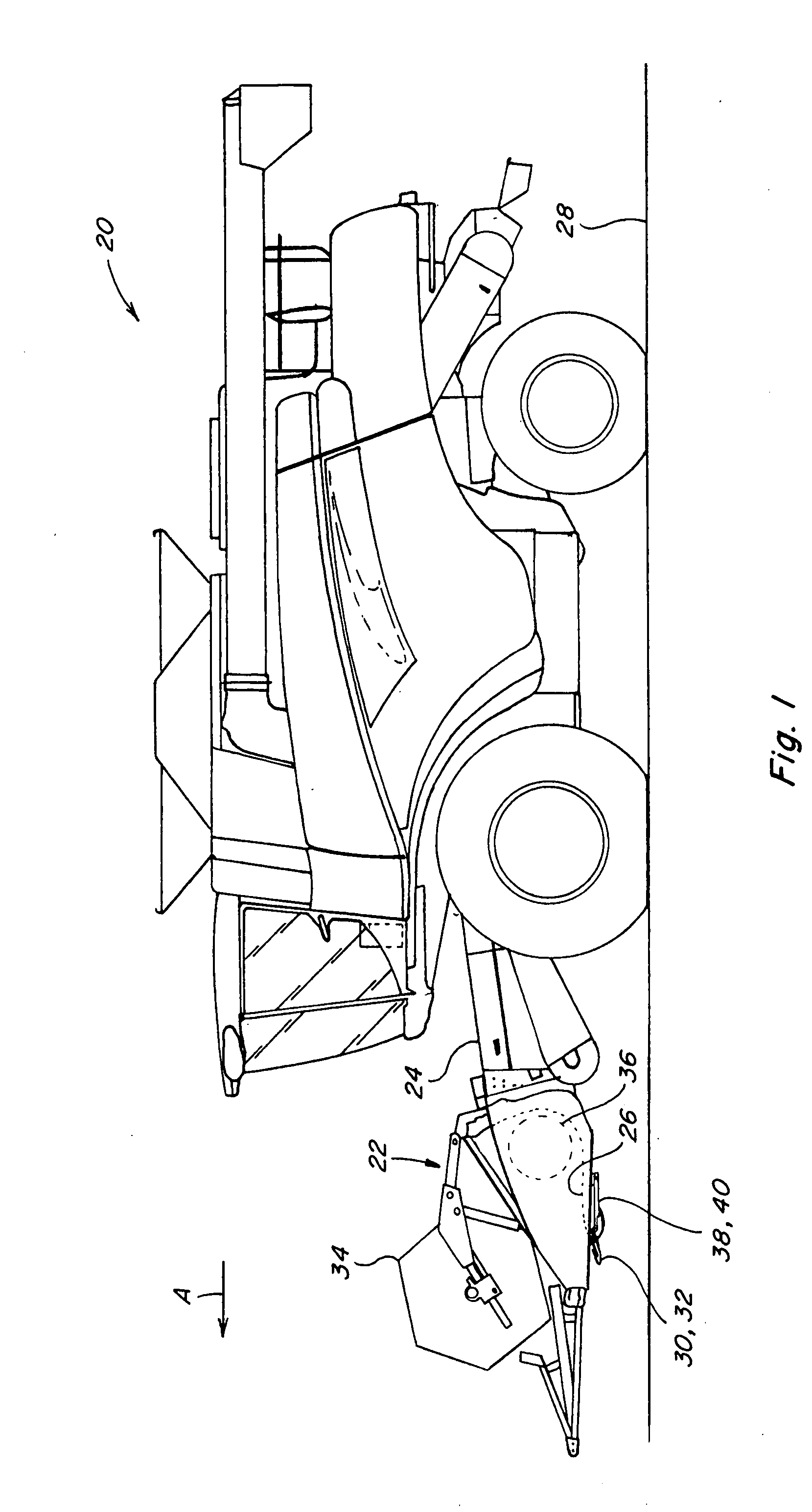
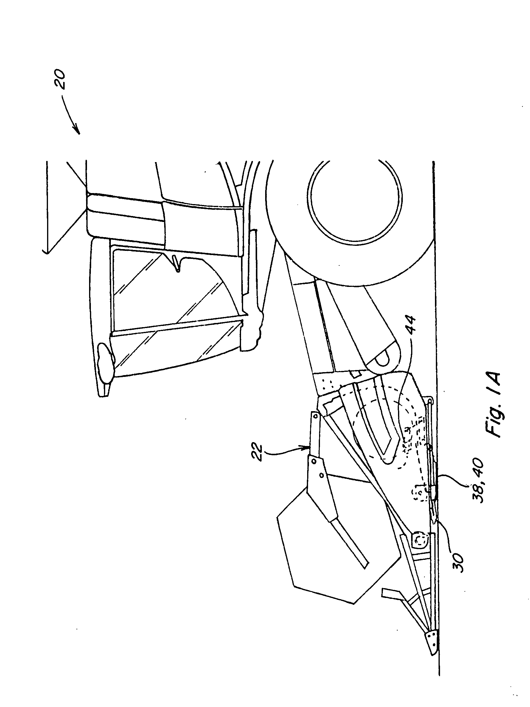
[0029]Turning now to the drawings wherein a preferred embodiment of the invention is shown, in FIG. 1, a conventional, well known agricultural combine 20 is shown including a conventional header 22 supported on a feeder 24, for cutting or severing crops such as, but not limited to, legumes such as soybeans and small grains such as wheat, and inducting the severed crops into feeder 24 for conveyance into combine 20 for threshing and cleaning, in the well known manner as combine 20 moves forwardly over a field, as denoted by arrow A. Header 22 includes a bottom or pan 26 which is supported in desired proximity to a ground surface 28 of a field during the harvesting operation, and an elongate, sidewardly extending cutter bar 30 supporting elongate, reciprocally movable sickle knives 32 disposed along a forward edge of pan 26 which sever the crop for induction into header 22. Header 22 includes an elongate, sidewardly extending reel 34 disposed above pan 26 and rotatable in a direction ...


PUM


Abstract

A control system for a header for an agricultural harvesting machine such as a combine, providing features including an automatic reel position control operable to provide at least one selectable predetermined cutter bar and reel position combination, and which can also automatically control height and/or fore and aft positions of the reel responsive to cutter bar movements, as required, for purposes such as for maintaining and/or optimizing the reel/cutter bar relationship for a particular crop and/or condition, and for avoiding interference between the tines or fingers of the reel and the sickle of the cutter bar, and possible damage to the tines and/or sickles, and slippage of the reel and/or sickle drive, that can result.

Description

TECHNICAL FIELD[0001]This invention relates generally a control system for a header for an agricultural harvesting machine such as a combine, and a method of operation of the same, and, more particularly, to a control system and method providing features including an automatic reel position control operable to provide at least one selectable cutter bar and reel position combination, and which can also automatically control height and / or fore and aft positions of the reel responsive to cutter bar movements.BACKGROUND ART[0002]On a grain type header, a cutter bar typically extends across a lower front end of the header and includes a sidewardly reciprocating sickle for cutting crops. A gathering reel rotatable about a sidewardly extending axis is typically disposed above and forwardly of the cutter bar, and the type of reel of most concern here is commonly referred to as a pick up type reel will include generally radially outwardly extending tines or fingers which essentially function...

Claims


Application Information

Patent Timeline
IPC IPC(8): A01D34/00
CPCA01D41/141
Inventor BICH, GARY L.YDE, LUC
Owner CNH IND AMERICA LLC
Why Eureka
Try Eureka