
Deposition Apparatus With Guide Roller For Long Superconducting Tape

Inactive Publication Date: 2009-04-30
KOREA ELECTROTECH RES INST
View PDF4 Cites 10 Cited by
  • Summary
  • Abstract
  • Description
  • Claims
  • Application Information

AI Technical Summary

Benefits of technology

[0009]Accordingly, the present invention has been made keeping in mind the above problems occurring in the prior art, and an object of the present invention is to provide a deposition apparatus with a guide roller for a long superconducting tape, which deposits a superconducting layer while maintaining constant tension when the tape is thermally deposited, thus preventing the tape from being deformed because of the difference in the thermal expansion and contraction of the tape resulting from non-uniform tension.
[0010]Another object of the present invention is to provide a deposition apparatus with a guide roller for a long superconducting tape, which prevents tension from increasing even if a large amount of tape is wound around a drum and the guide roller, thus allowing the long superconducting tape to be deposited without damage, and which performs a deposition process without requiring replacement of the drum with another one, even if the length of the tape is increased.

Problems solved by technology

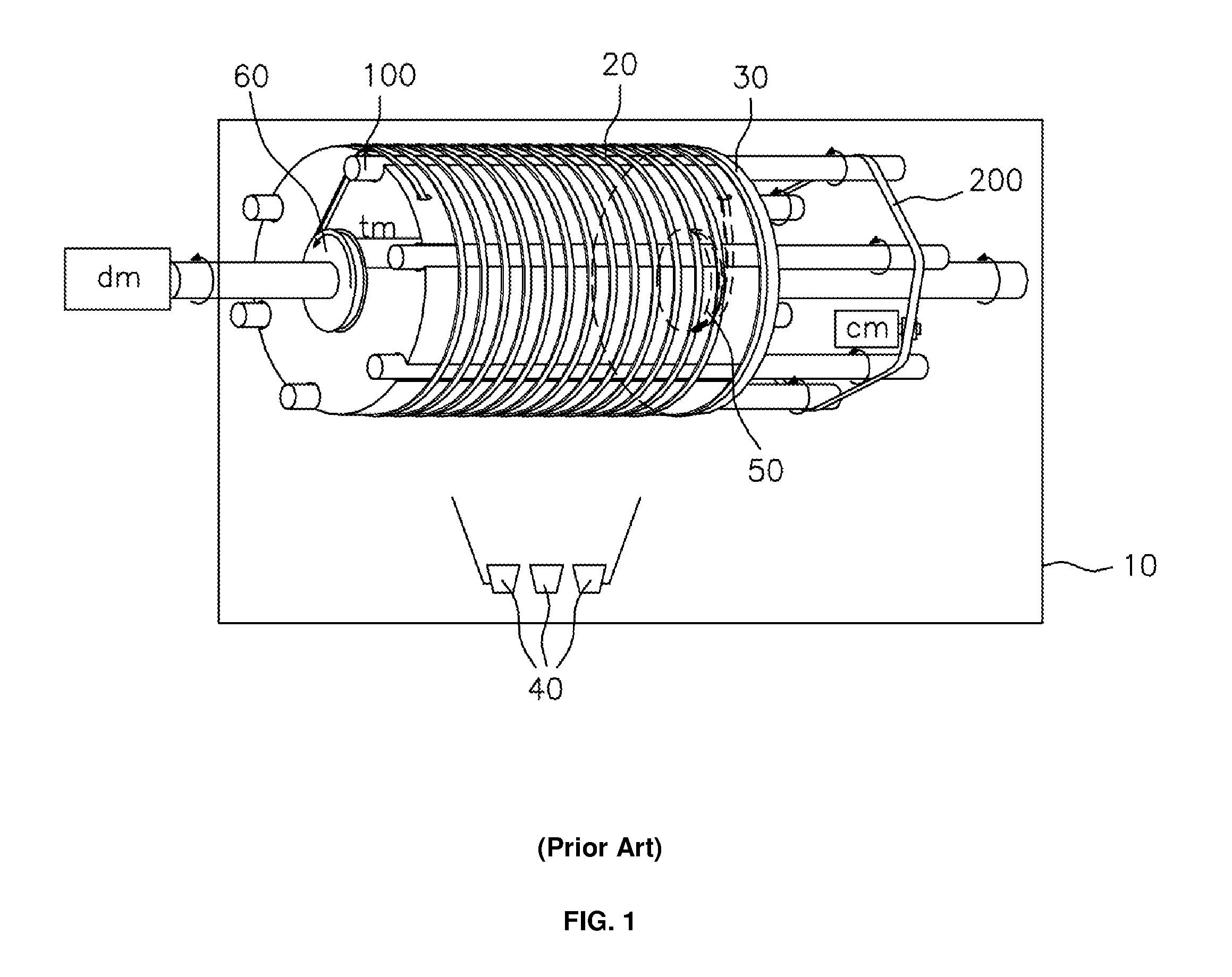
However, the conventional deposition apparatus for the long superconducting tape using the drum is problematic in that it uses the slip rollers, but tension acting on the tape varies according to the contact angle, which is determined depending on the shape of the drum and the slip rollers, so that the tape may be extended or deformed at different rates, and may sag or be deformed due to the difference in thermal expansion and contraction according to tension acting on the tape when it is deposited.
Further, the conventional deposition apparatus for the long superconducting tape is problematic in that the length of the fed superconducting tape depends on the diameter of the drum, so that, when the superconducting tape that is to be deposited is long, the drum must be replaced with a drum having a large diameter.
Further, the larger the tape that is wound, the more tension is applied to the tape because of bearing friction, and thus the tape may be deformed.

Method used


Image

  • Deposition Apparatus With Guide Roller For Long Superconducting Tape
  • Deposition Apparatus With Guide Roller For Long Superconducting Tape
  • Deposition Apparatus With Guide Roller For Long Superconducting Tape

Examples


Embodiment Construction

[0018]Reference now should be made to the drawings, in which the same reference numerals are used throughout the different drawings to designate the same or similar components.

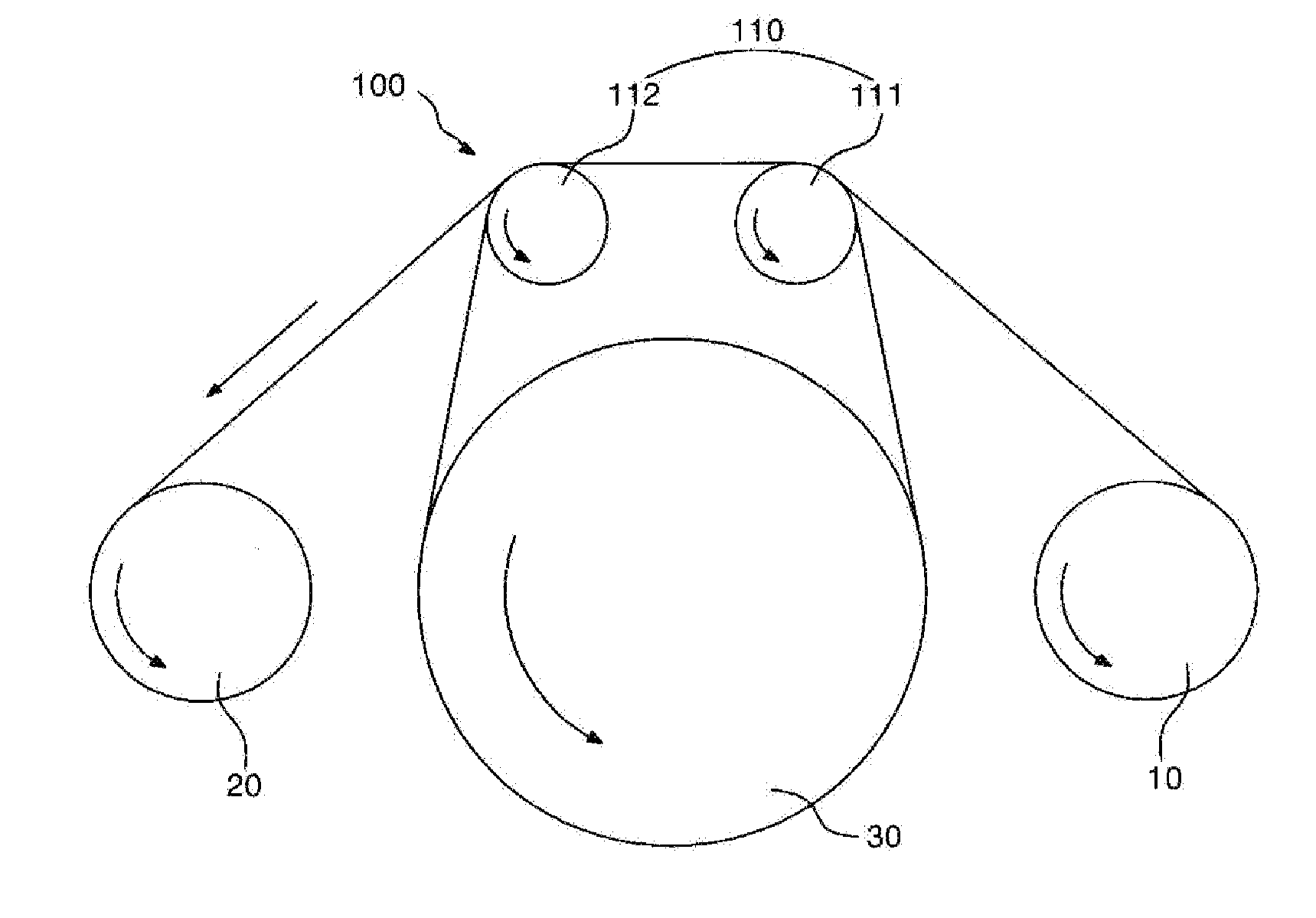
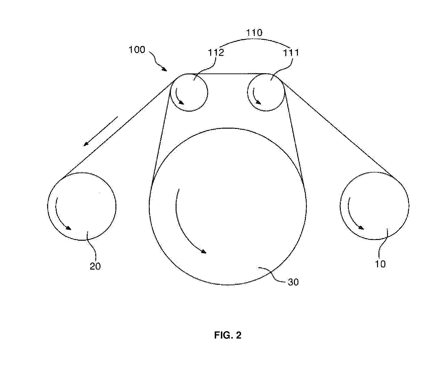
[0019]FIG. 2 is a sectional view showing a deposition apparatus with a guide roller for a long superconducting tape, according to the present invention, and FIG. 3 is a plan view showing the deposition apparatus with the guide roller for the long superconducting tape, according to the present invention.

[0020]As shown in FIGS. 2 and 3, the deposition apparatus according to the present invention includes a supply reel 10, a feed and deposition unit 100, and a collection reel 20. The supply reel 10 functions to supply the tape. The feed and deposition unit 100 is rotated to wind the tape, thus feeding and depositing the tape which is supplied to the feed and deposition unit 100. The collection reel 20 functions to wind and collect the superconducting tape which is deposited via the feed and deposition unit 100.

[0...


PUM

PropertyMeasurementUnit
Thicknessaaaaaaaaaa
Angleaaaaaaaaaa
Widthaaaaaaaaaa

Abstract

Disclosed herein is a deposition apparatus with a guide roller for a long superconducting tape. The deposition apparatus has a supply reel which is provided in a vacuum chamber and rotated to supply the tape, a feed and deposition unit which is spaced apart from the supply reel and vacuum deposits a superconducting layer on the tape while feeding the tape, and a collection reel which is spaced apart from the feed and deposition unit and is rotated to collect the vacuum-deposited tape. The feed and deposition unit includes a drum which is rotated to wind the tape on a predetermined portion of an outer circumference of the drum several times, thus feeding the tape, and a guide roller which is spaced apart from the drum, includes a plurality of rollers each having on an outer circumference thereof grooves and protrusions at regular intervals, and is inclined at a predetermined angle with respect to a rotating shaft of the drum by a sum of a width of the tape and a thickness of each of the protrusions, with the tape passing over an outer circumference of the guide roller. The invention deposits a superconducting layer while maintaining constant tension when the tape is thermally deposited, thus preventing the tape from being deformed because of the difference in the thermal expansion and contraction of the tape resulting from non-uniform tension.

Description

FIELD OF THE INVENTION[0001]The present invention relates generally to a deposition apparatus with a guide roller for a long superconducting tape and, more particularly, to a deposition apparatus with a guide roller for a long superconducting tape, which feeds the long superconducting tape via the guide roller, thus reducing damage to the long superconducting tape, and allowing the long superconducting tape to be deposited without deforming the long superconducting tape.BACKGROUND OF THE INVENTION[0002]Generally, a superconducting material is used for a transmission line, a motor, a multipurpose pancake coil, a power generator, or a magnet, which belong to the power application equipment field. In order for the superconducting material to be used for the power application equipment field, the loss of alternating current of the superconducting material must be minimized. To this end, a superconducting tape which is flexible and is several hundreds of meters in length is used. It is k...

Claims


Application Information

Patent Timeline
IPC IPC(8): C23C14/24
CPCH01L39/2422C23C14/562H10N60/0296H01L21/02H01L21/00
Inventor HA, HONG SOOOH, SANG SOOHA, DONG WOOSONG, KYU JUNGKO, ROCK KILKIM, HO SUP
Owner KOREA ELECTROTECH RES INST
Learn More