Belt for a corrugator machine having a friction coefficiet reduced driven side

a corrugator machine and friction coefficiet technology, applied in the field of corrugator machine belts, can solve the problems of increasing friction loss between the fabric belts, and reducing friction work, so as to reduce friction work, reduce friction coefficient, and reduce friction work

Active Publication Date: 2009-04-30
MUHLEN SOHN
View PDF2 Cites 2 Cited by
  • Summary
  • Abstract
  • Description
  • Claims
  • Application Information

AI Technical Summary

Benefits of technology

[0018]According to a feature of the invention, a belt for a corrugator machine is provided which comprises a fabric of warp fibers and weft fibers. The belt has a paper side facing toward the corrugated board to be manufactured and a driven side facing away from the corrugated board. The paper side of the fabric belt lies against the corrugated board whereas a drive acts on the driven side of the fabric belt which drive introduces tension forces into the belt which are necessary for the longitudinal movement of the fabric belt. The arrangement of a material for reducing the coefficient of friction on the belt side, which defines the driven side, leads to reduced friction work between the pressure elements and the driven side of the fabric belt in the heating and pressure zone. The friction coefficient reducing material has a lower coefficient of friction than the material forming the fabric belt.

Problems solved by technology

The friction loss, however, increases between the fabric belt, which runs with the corrugated board through the heating and pressure zone, and the press shoes of the individual pressure elements.

Method used


Image

  • Belt for a corrugator machine having a friction coefficiet reduced driven side
  • Belt for a corrugator machine having a friction coefficiet reduced driven side
  • Belt for a corrugator machine having a friction coefficiet reduced driven side

Examples


Embodiment Construction

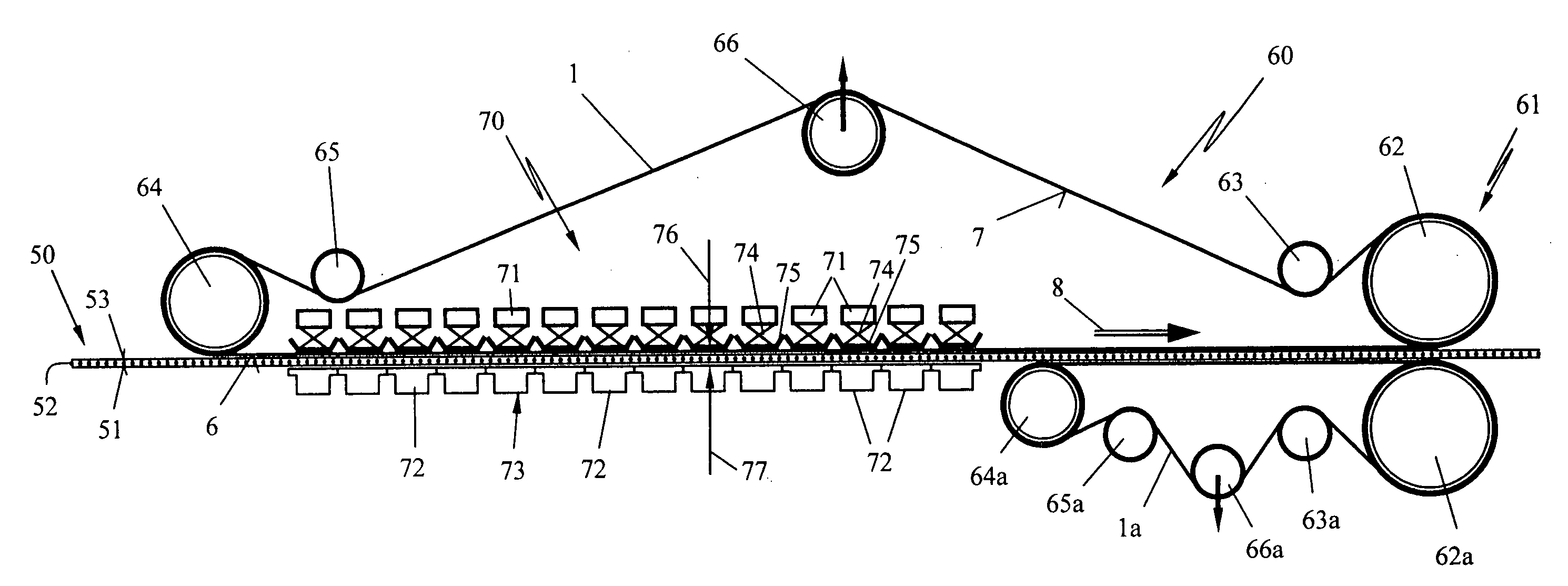
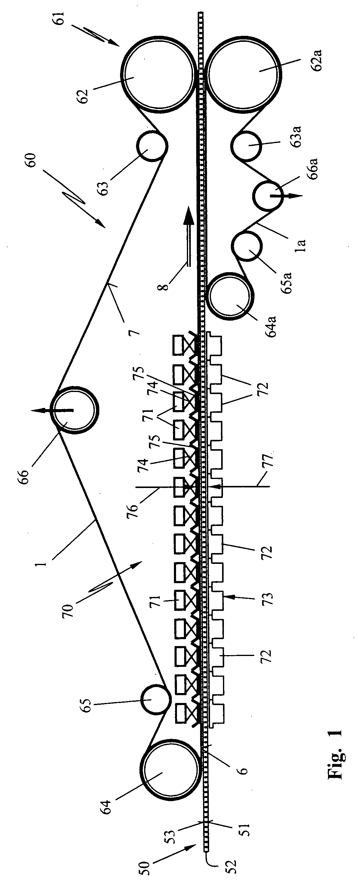
[0026]The corrugator machine 60 shown schematically in FIG. 1, functions to manufacture corrugated board 50. The corrugated board 50 comprises a middle layer 52 of corrugated material and covering outer layers 51 and 53 of smooth material. The middle layer 52 is bonded to the outer layers 51 and 53 under pressure and heat and are preferably bonded to each other with adhesive.

[0027]For this purpose, a pressure zone 70 is formed in the corrugator machine which comprises individual pressure elements 71 and corresponding countersupports 73. In the embodiment shown, fourteen pressure elements and fourteen countersupports 73 lie one behind the other in the transport direction 8. Each pressure element 71 has a press shoe 75 corresponding thereto. The press shoe 75 is pressed via a correspondingly configured spring element 74 with adjustable force tightly against the countersupport 73. Heaters 72 are formed in the countersupports 73. Preferably, a hot-air heater is provided. Electrical heat...


PUM

PropertyMeasurementUnit
wrap angleaaaaaaaaaa
coefficient of sliding frictionaaaaaaaaaa

Abstract

The invention relates to a belt for a corrugator machine for making corrugated board (50) wherein at least a middle layer (52) of corrugated material is joined under pressure to cover layers (51, 53) of smooth material to form the corrugated board (50). The belt (1) is made of a fabric of warp fibers and weft fibers (4) and has a paper side facing toward the corrugated board (50) to be manufactured. The paper side (6) lies against the corrugated board (50). A driven side (7) lies facing away from the corrugated board (50). The corrugator machine has a pressure zone (70) which includes a pressure element (71) and a countersupport (73). The corrugated board (50) together with the contact engaging fabric belt (1) pass between the pressure element (71) and the countersupport (73). A drive (61) is provided on the driven side (7) of the belt to generate the tension forces acting in the longitudinal direction of the belt. To reduce the friction loss in the pressure zone, a material is provided on the driven side (7) of the fabric belt (1) for reducing the coefficient of friction of the belt side defining the driven side (7).

Description

CROSS REFERENCE TO RELATED APPLICATION[0001]This application claims priority of European patent application no. 07021154.5, filed Oct. 30, 2007, the entire content of which is incorporated herein by reference.FIELD OF THE INVENTION[0002]The invention relates to a belt for a corrugator machine for manufacturing corrugated board.BACKGROUND OF THE INVENTION[0003]A belt of the kind referred to above is known from U.S. Pat. No. 5,785,621 and comprises a fabric of warp fibers and weft fibers. The belt has an outer paper side which faces toward the corrugated board to be manufactured. The paper side lies against the corrugated board and the belt has a driven side lying so as to face away from the corrugated board. Tension forces are introduced into the fabric belt via the driven side thereof.[0004]In known corrugator machines, the corrugated board lies between two fabric belts and is pulled through a heating and pressure zone whereat the bonding of the individual layers of the corrugated b...

Claims


Application Information

Patent Timeline
Patent Type & Authority Applications(United States)
IPC IPC(8): B31F1/16
CPCD21F1/0045Y10S162/902Y10T442/2311Y10T442/3228
Inventor BELLA, HARTMUT
Owner MUHLEN SOHN
Why Eureka
Try Eureka