Side-flexing conveyor chain with pivoting slats and related methods

a conveyor chain and slat technology, applied in the field of conveyor art, can solve the problems of affecting reducing the service life of the conveyor chain, so as to reduce the wear of the slats, and avoid direct frictional contact.

Inactive Publication Date: 2009-04-30
SPAN TECH
View PDF91 Cites 20 Cited by
  • Summary
  • Abstract
  • Description
  • Claims
  • Application Information

AI Technical Summary

Benefits of technology

[0014]Preferably, a spacer is provided for preventing adjacent slats from directly contacting each other when the chain is in the compressed condition. This is done to avoid direct frictional contact among and reduce wear on the slats. Most preferably, the spacer comprises a receiver for receiving a first side of the slat. One of the connectors may carry the receiver and, ideally, a first receiver is supported by a first connector and a second, adjacent receiver is supported by a second connector. In use, the first receiver engages the second receiver when the chain is at least partially in the compressed condition.
[0015]In accordance with yet another aspect of the invention, a modular link conveyor chain capable of side flexing and moving along a forward run and a return run in an endless path incorporates slats. The chain comprises a plurality of links arranged in rows spaced apart in a conveying direction, the links in at least a first row including first apertures and the links in at least a second row including second, oversized apertures for aligning with the first apertures when interdigitated with the links in the first row. A connector associates with each of the first and second apertures in the first and second rows of links. A slat is mounted to each connector so as to be capable of at least partially nesting with the next-adjacent slat when the chain side-flexes or undergoes longitudinal compression. Preferably, the chain further includes a spacer for preventing adjacent slats from directly contacting each other in the compressed condition in order to avoid direct frictional contact among and reduce wear on the slats.

Problems solved by technology

However, many of these items, such as breads and other baked goods require cooling prior to packaging.
Additionally, these food products are often soft and fragile, thereby requiring special care during transportation through the production facility to avoid damage.
Such a conveying surface does not, however, maximize the amount of thermal transfer to the underside of the articles being conveyed.
This can be deleterious for cooling items during conveyance, such as baked goods or frozen foods being packaged at a downstream location.
Soft goods also tend to conform to the conveying surface, if interrupted, which can lead to unwanted vestiges.
Another limitation with prior art chains with laterally repeating links is the creation of multiple crevasses and recesses in which debris and residue can become lodged.
Despite the existence of various types of belt or chain “washers,” it remains difficult to ensure that the cleaning is as thorough as possible in view of the large number of open spaces in the conveying surface of a typical modular link chain.
Such thorough cleaning may be crucial in certain situations (such as food processing), but may also contribute substantially to the operating expense.
Additionally, many production facilities also have limited floor space, thereby making efficient use of the space available imperative.
While this approach is advantageous in certain respects, it is not without significant limitations.
This greatly limits its usefulness (including in connection with spiral-type freeze conveyors).
Another limitation is that the elements are in direct contact along the forward run, and are thus subject to frictional wear.
The free, uncontrolled pivoting of the elements may also render them susceptible to reaching undesirable positions and becoming “caught up” with adjacent elements.

Method used


Image

  • Side-flexing conveyor chain with pivoting slats and related methods
  • Side-flexing conveyor chain with pivoting slats and related methods
  • Side-flexing conveyor chain with pivoting slats and related methods

Examples


Embodiment Construction

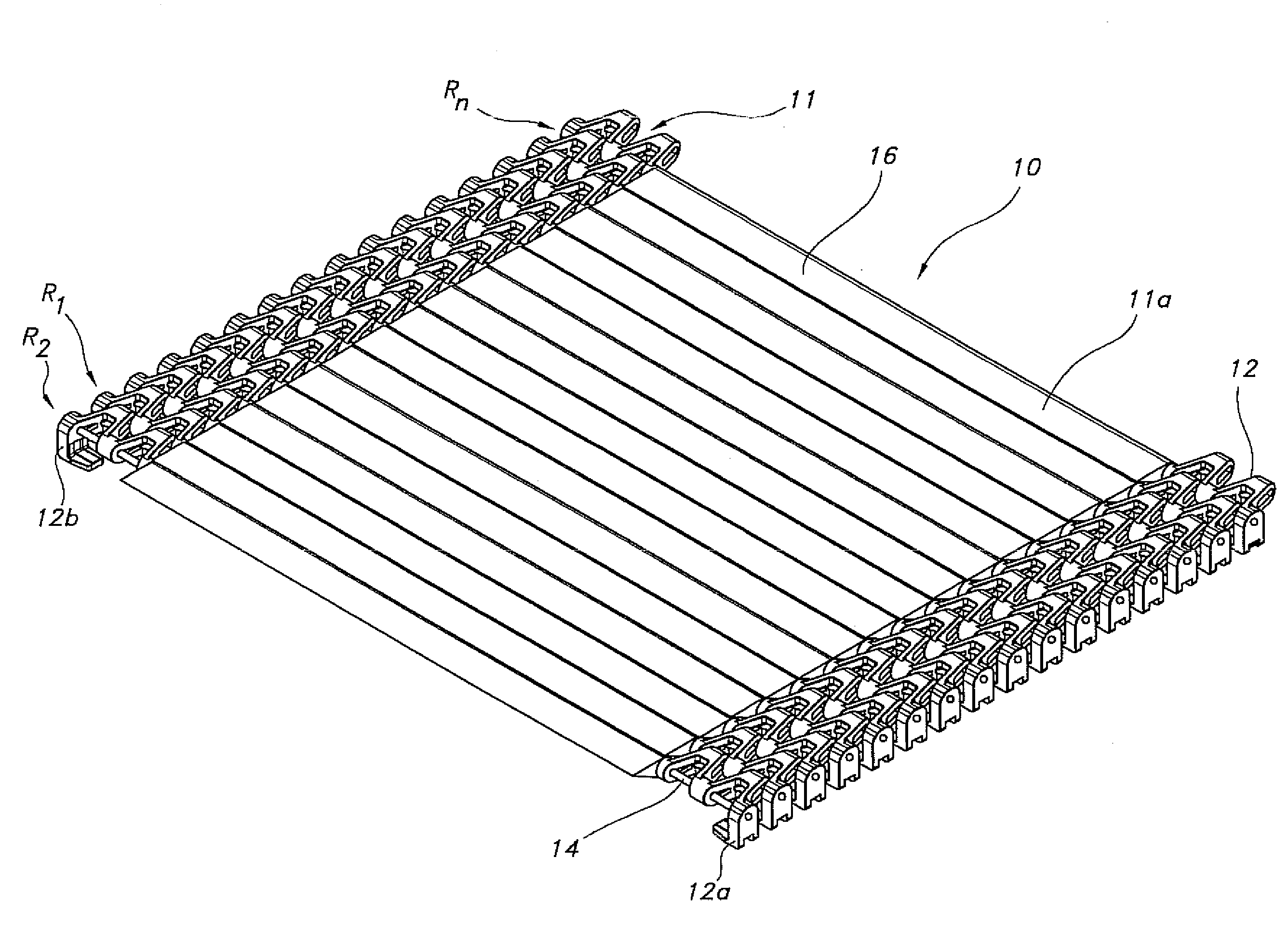
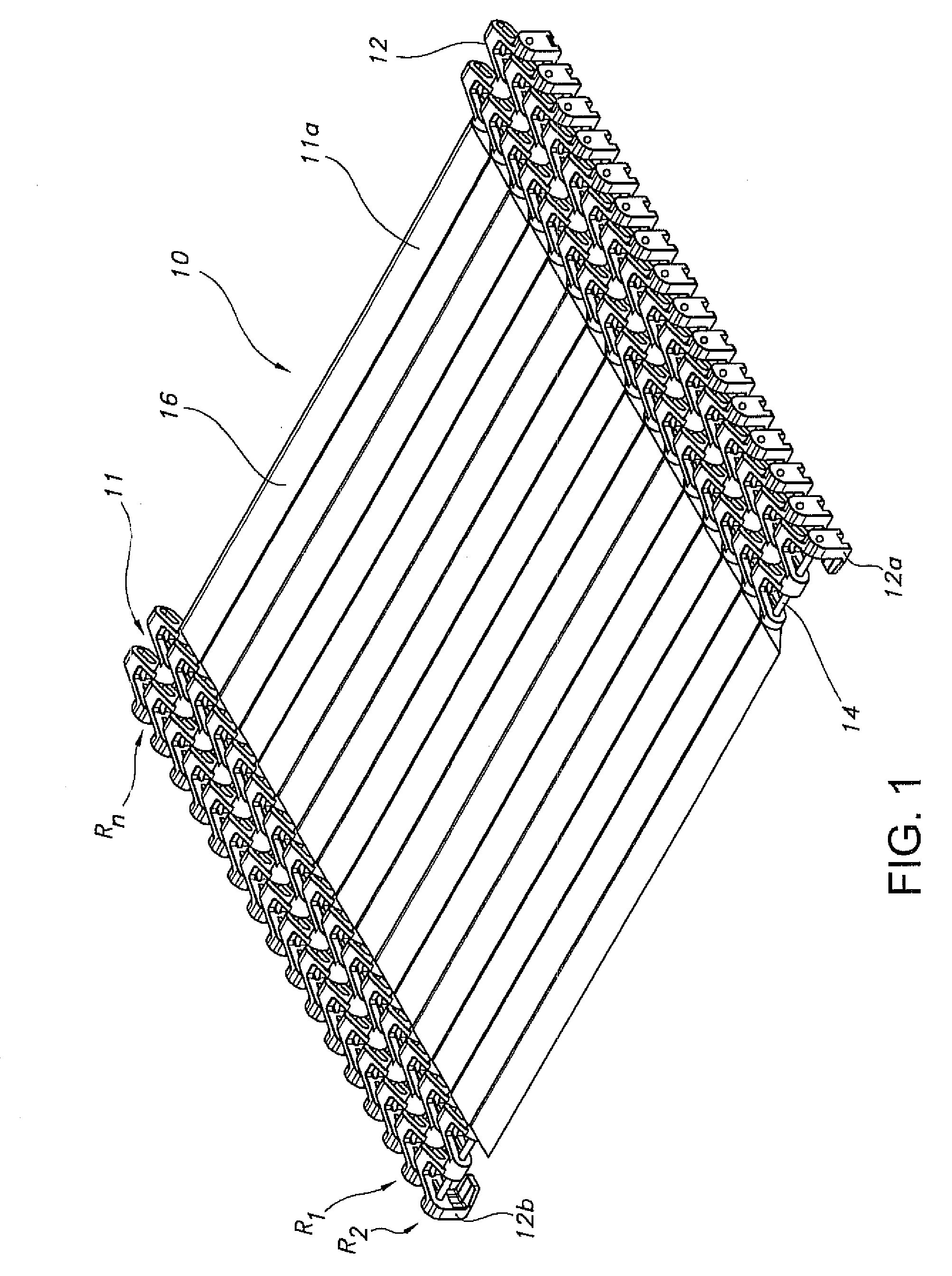
[0031]Reference is now made to FIG. 1, which depicts a conveyor belt or chain 10 including a conveying surface 11 for engaging and supporting articles. In this particular embodiment, the chain 10 comprises modular links in the form of side guide links 12 arranged in spaced apart rows R1 . . . Rn, which thus partially create the conveying surface 11. As should be appreciated, the chain 10 may form part of an overall conveyor system, which may include guide rails for guiding the chain as well as a drive system incorporating a sprocket or roller for driving the chain. In such a system, the chain 10 may be driven along an endless path between a forward run F and a return run N, which may be vertically offset or otherwise.

[0032]Adjacent rows R1, R2 of the side links 12 interconnect via transversely extending connectors 14, which are also referred to in the vernacular as “cross rods,”“hinge pins,” etc. Specifically, as shown in FIGS. 1, 7a, and 7b, each side link 12 includes a plurality o...


PUM

PropertyMeasurementUnit
thermal transferaaaaaaaaaa
areaaaaaaaaaaa
thermally conductiveaaaaaaaaaa

Abstract

In one aspect, a modular link conveyor chain including slats is capable of assuming a compressed and an expanded condition so as to permit side-flexing while moving along a forward run and a return run in an endless path. The chain is formed of links arranged in rows spaced apart in the conveying direction, the links of a first row including aligned apertures and the links of a second row including oversized apertures, such as slots, for aligning with the aligned apertures of the links in the first row. A first connector is associated with the corresponding apertures to interconnect the first and second rows of links. At least one elongated slat is mounted to the connector. The slat maybe mounted for pivoting movement between a first position forming at least part of a conveying surface along the forward run, and a second position along the return run.

Description

[0001]This application claims the benefit of U.S. Provisional Patent Application Ser. No. 60 / 802,898, filed May 24, 2006, the disclosure of which is incorporated herein by reference.TECHNICAL FIELD[0002]The present invention relates generally to the conveyor art and, more particularly, to a side-flexing conveyor chain incorporating pivoting elongated slats and related methods.BACKGROUND OF THE INVENTION[0003]Conveyor systems form an integral part of modern production facilities. Such systems are especially beneficial in the food processing and article packaging industries, where it is often desirable to move articles to and from different areas of the production facility to undergo various manufacturing / packaging operations. For example, many food manufactures require transportation of food items from a baking area to a position for final packaging. However, many of these items, such as breads and other baked goods require cooling prior to packaging. Additionally, these food product...

Claims


Application Information

Patent Timeline
Patent Type & Authority Applications(United States)
IPC IPC(8): B65G17/40B21L9/06B65G47/00
CPCB65G17/063Y10T29/49826B65G17/16B65G17/068B65G2207/12
Inventor LAYNE, JAMES L.WARD, LEWIS W.THOMAS, B. KEITHRUSSELL, MARK D.
Owner SPAN TECH
Why Eureka
Try Eureka