Output control apparatus of generator

a technology of output control and generator, which is applied in the direction of electric generator control, dynamo-electric converter control, dynamo-electric brake control, etc., can solve the problem of not being able to maintain the electric current flowing through the field, and achieve the waveform of the generator output

Inactive Publication Date: 2009-04-30
HONDA MOTOR CO LTD
View PDF34 Cites 1 Cited by
  • Summary
  • Abstract
  • Description
  • Claims
  • Application Information

AI Technical Summary

Benefits of technology

[0014]According to the present invention having the first through fourth features, since field current flowing through the field winding can be detected by the electric current detection means, a variation in the field current due to mutual interaction of the field winding and the power generation winding can be detected directly. Further, the field current being detected can be converged with an appropriate target electric current by impedance adjustment of the circuit including the field winding by the impedance adjustment means. Accordingly, different from conventional technology in which the field current is turned ON / OFF by a switching element, the flywheel diode for surge voltage absorption generated at energizing stop is unnecessary. As a result, influences of the electric current flowing through the flywheel diode are removed, variation in the field current can be reflected accurately to controls, and therefore, the field current can be stabilized and output of the generator winding, i.e., waveform of the generator output, can be improved.

Problems solved by technology

Therefore, with the control apparatus having the flywheel diode 112, it is not easy to maintain the electric current flowing through the field winding 102 constant.

Method used


Image

  • Output control apparatus of generator
  • Output control apparatus of generator
  • Output control apparatus of generator

Examples


Embodiment Construction

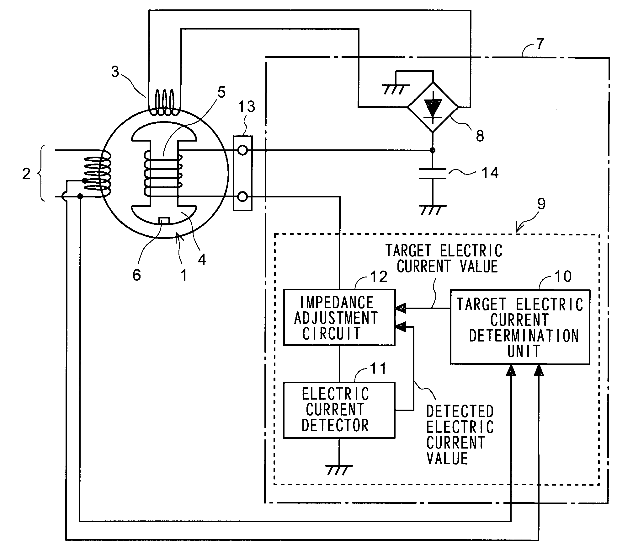
[0022]Referring now to the drawings, the present invention will be explained in detail hereafter. FIG. 1 is a drawing showing composition of primary components of the generator including output control apparatus relating to one embodiment of the present invention. A generator 1 is an AC generator well known to the art and includes a power generation winding 2 and an excitation winding 3 provided at stator side, and a field winding 5 being wound around a rotor 4. A permanent magnet 6 is mounted to the rotor 4 for generation of excitation current on the excitation winding 3. The rotor 4 is driven by a driving source such as engine (not shown).

[0023]An automatic voltage regulator 7 includes a rectifier 8 and an electric current control unit 9. Both ends of the excitation winding 3 are connected to input side of the rectifier 8. The electric current control unit 9 includes a target electric current determination unit 10, an electric current detector 11, and an impedance adjustment circu...


PUM


Abstract

Output waveform of the generator is improved through stabilization of field current by removing flywheel diode used to be required for automatic voltage regulator. Output electric current of excitation winding 3 is rectified by rectifier 8 and is supplied to field winding 5 of rotor 4. Impedance adjustment circuit 12 is provided to circuit where field current flows. Target electric current determination unit 10 determines target electric current (target field current) used to control output voltage of power generation winding 2 to the reference voltage. Impedance adjustment circuit 12 increases or decreases the impedance of field current circuit so that the field current detected by electric current detector 11 converges with target electric current.

Description

BACKGROUND OF THE INVENTION[0001]1. Field of the Invention[0002]The present invention relates to an output control apparatus of a generator, and particularly to an output control apparatus of a generator suitable for further improvement of output voltage waveform by maintaining an electric current flowing a field winding constant.[0003]2. Description of the Related Art[0004]In a power generation control apparatus of an alternating-current (AC) generator which includes a power generation winding, excitation winding, and field winding, and rectifies electric current generated in the excitation winding and supplies the same to the field winding, automatic voltage regulator is known in the art which maintains a voltage output from the power generation winding to a predetermined voltage by controlling the electric current supplied to the excitation winding.[0005]FIG. 6 is a drawing showing composition of primary components of the AC generator equipped with conventional automatic voltage ...

Claims


Application Information

Patent Timeline
Patent Type & Authority Applications(United States)
IPC IPC(8): H02P9/30
CPCH02P9/30
Inventor NAKADA, YASUHIROINOUE, TOSHIO
Owner HONDA MOTOR CO LTD
Why Eureka
Try Eureka