Augmented passive tracking of a moving emitter

a passive tracking and emitter technology, applied in direction finders, instruments, communication jamming, etc., can solve the problems of preventing the subsequent convergence of the true target track, the failure of bearing-only estimators to initialize correctly, and the inability to uniquely associate the sequence of bearing measurements

Active Publication Date: 2009-04-30
NORTHROP GRUMMAN SYST CORP
View PDF40 Cites 26 Cited by
  • Summary
  • Abstract
  • Description
  • Claims
  • Application Information

AI Technical Summary

Benefits of technology

[0024]Radar systems do a superb job accurately tracking targets. They achieve their accuracy by measurements involving range information as well as azimuth and by f

Problems solved by technology

A problem in bearings-only estimation is a sequence of bearing measurements cannot be uniquely associated with the correct emitter position and velocity without the observer undergoing special accelerations.
This leads to the frequent failure of bearings-only estimators to initialize correctly and prevents their subsequent convergence to the true target track.
Further, even when they do converge the target is likely to subsequently undergo an acceleration that causes a constant-velocity estimator to break track or diverge.
Hence the method ameliorates the observability problem but does not typically solve it with a unique initial target state.
Although excellent for a bearings-only estimator tracking maneuvering targets, 5% accuracy is poor compared to tha

Method used


Image

  • Augmented passive tracking of a moving emitter
  • Augmented passive tracking of a moving emitter
  • Augmented passive tracking of a moving emitter

Examples


example 1

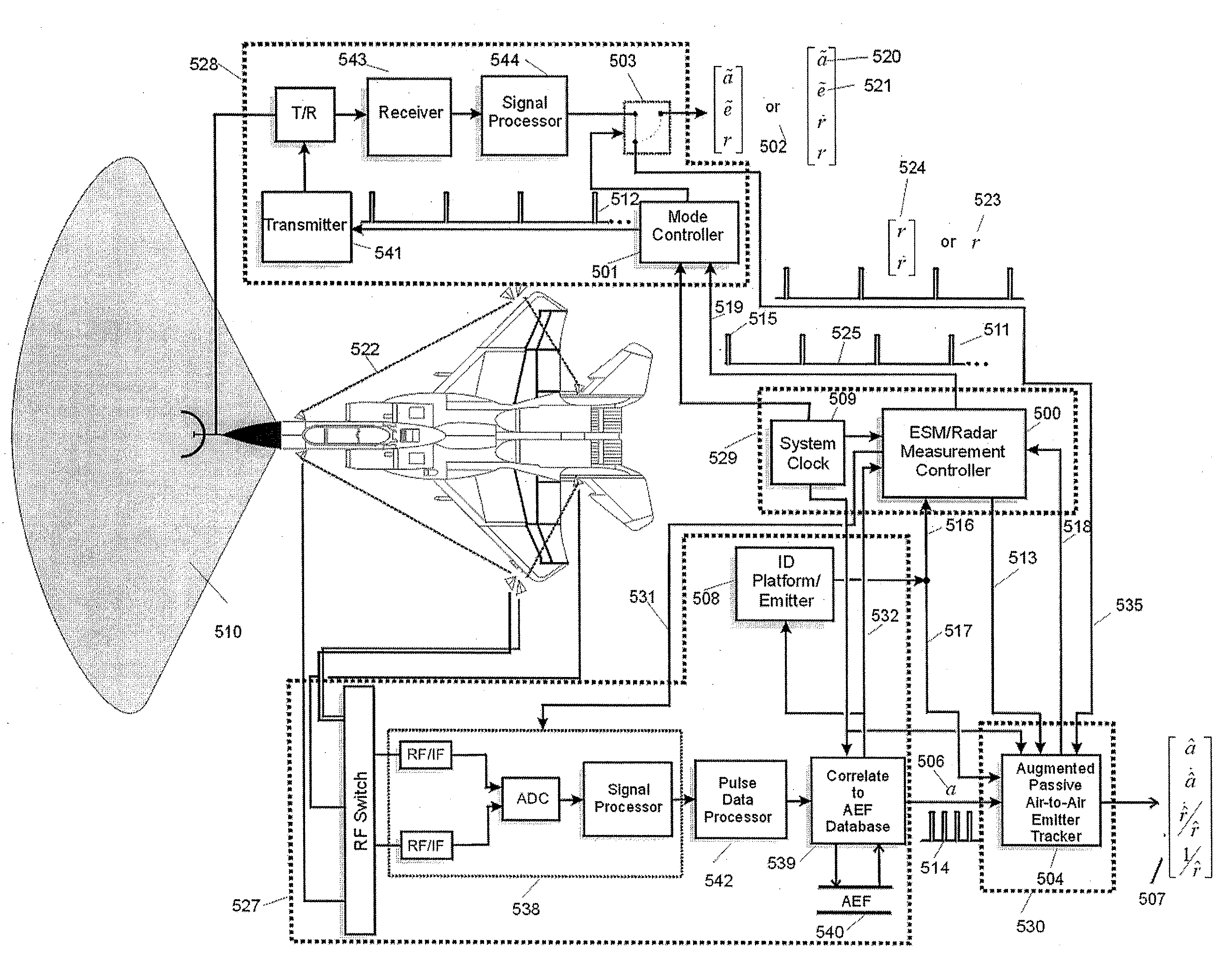
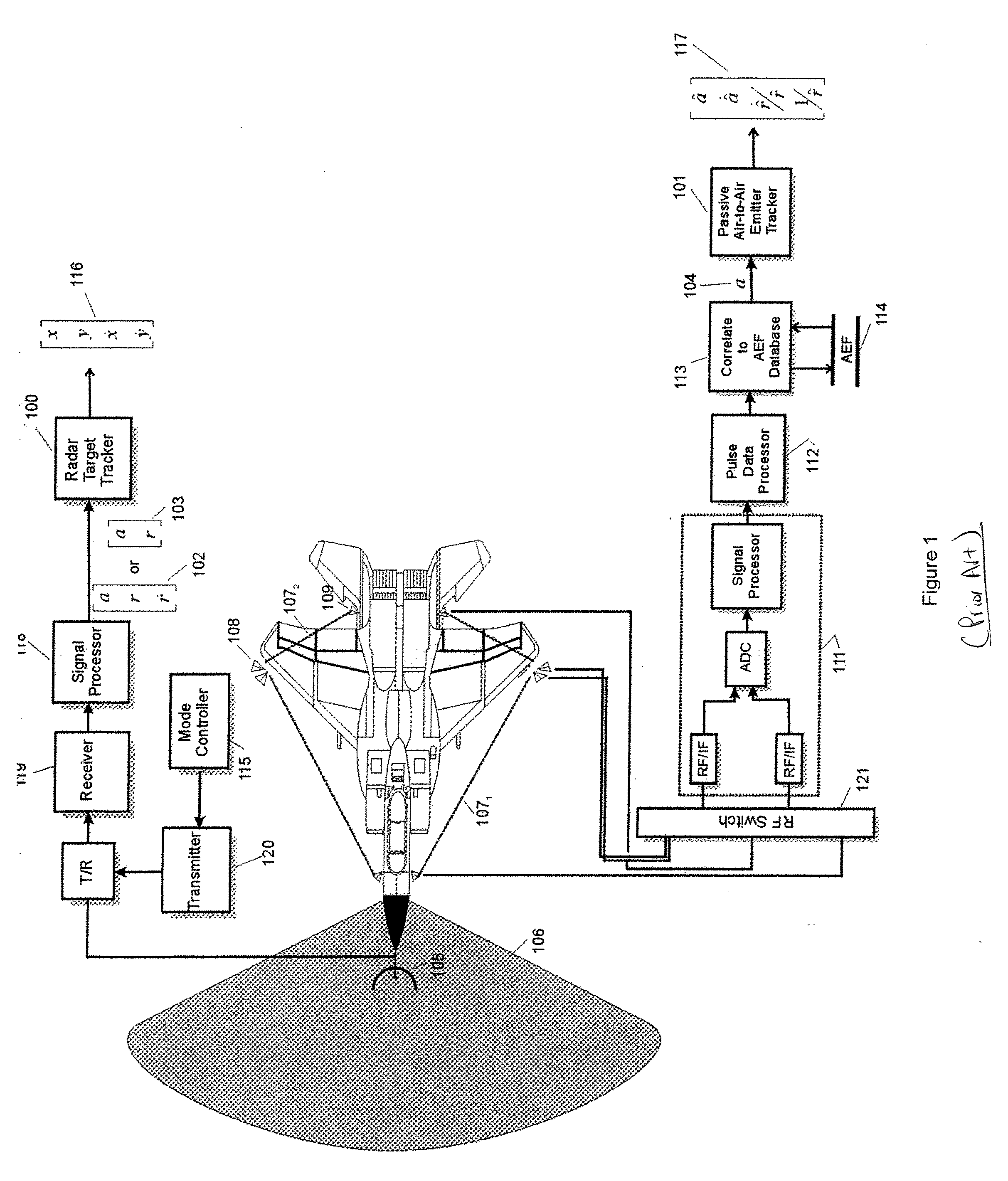
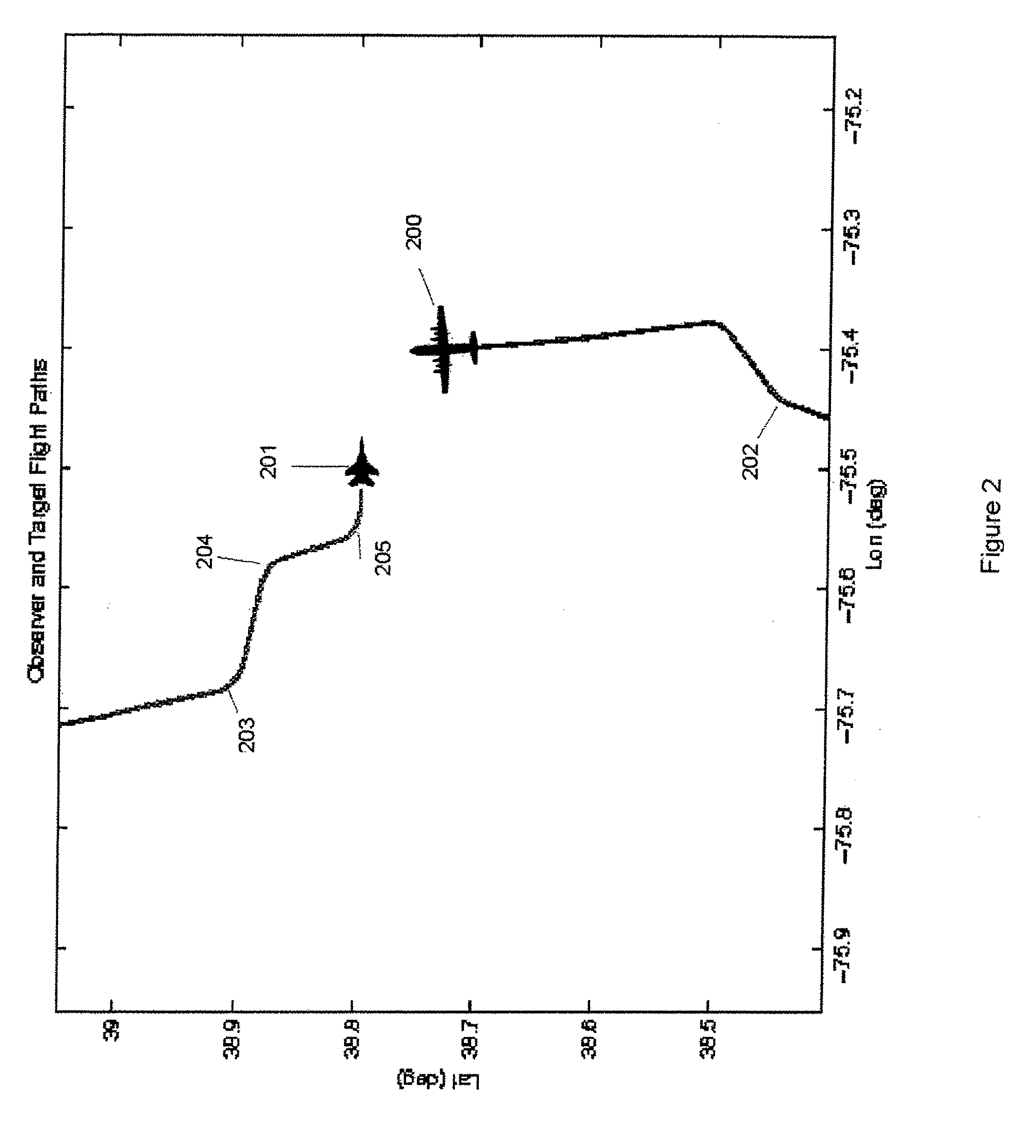
[0075]The following experimental results show performance improvement periodic augmented measurements achieved over strictly bearings only passive tracking in the Northrop Grumman Corporation flight test shown in FIG. 2. Both the ESM and radar systems shown in FIG. 1 were essentially implemented on aircraft 200, a BAC 1-11, and data from both systems were collected. Radar measurements 102 (FIG. 1) and ESM azimuth measurements 104 (FIG. 1) were saved with time tags utilizing a system clock similar to system clock 509 (FIG. 5). The measurements were subsequently processed using the method of this disclosure. Specifically, Controller 500 (FIG. 5) requested a fixed augmented measurement update rate of about 0.059 Hz, or every 17 seconds. The core ESM tracking filter implemented in Tracker 504 was the adaptive filter described in the '703 application. Using the bearings-only data this estimator generated FIG. 3 and FIG. 4 results previously discussed, with an azimuth 506 update rate of 1...


PUM


Abstract

In one embodiment, the disclosure relates to a method for estimating and predicting a target emitter's kinematics, the method including the steps of: (a) passively sampling, at a first sampling rate, an emitter signal to obtain at least one passively measured signal attribute for estimating the target kinematics; (b) inputting the passively measured signal attribute to an estimator at a first sampling rate; (c) determining a radar duty cycle for active radar measurements as a multiple of the first sampling rate, the multiple defining a duration between radar transmissions; (d) directing a radar system to make active target measurements at the determined duty cycle; (e) inputting to the estimator the active target measurements at the determined duty cycle, while continuously inputting the passively measured signal attributes.

Description

BACKGROUND[0001]1. Field of Invention[0002]This disclosure relates to the radar and Electronic Warfare Support Measures (ESM) systems located on a single aircraft. In one embodiment, the disclosure utilizes infrequently scheduled radar inputs to an otherwise passive ESM target tracking filter to enhance the performance of the passive tracker while minimizing the chance the radar is detected by ESM or Radar Warning Receivers (RWR) on other platforms.[0003]2. Description of Related Art[0004]FIG. 1 shows a typical conventional installation of the ESM and radar systems on tactical aircraft. In such installations the active detection system (represented by radar 105) and the passive detection system (represented by antenna pairs 108, 109) are essentially separate, as shown. Both systems have tracking filters 100 and 101. The inputs to the radar tracking filter 100 are target azimuth a, range r, and if the radar measures Doppler, radial rate {dot over (r)}. Hence, the input to the active ...

Claims


Application Information

Patent Timeline
IPC IPC(8): G01S13/00
CPCG01S3/46G01S13/86G01S13/723G01S7/021
Inventor ROSE, CONRAD
Owner NORTHROP GRUMMAN SYST CORP
Why Eureka
Try Eureka