
Methods and apparatuses for load balancing between multiple processing units

Active Publication Date: 2009-04-30
APPLE INC
View PDF15 Cites 235 Cited by
  • Summary
  • Abstract
  • Description
  • Claims
  • Application Information

AI Technical Summary

Benefits of technology

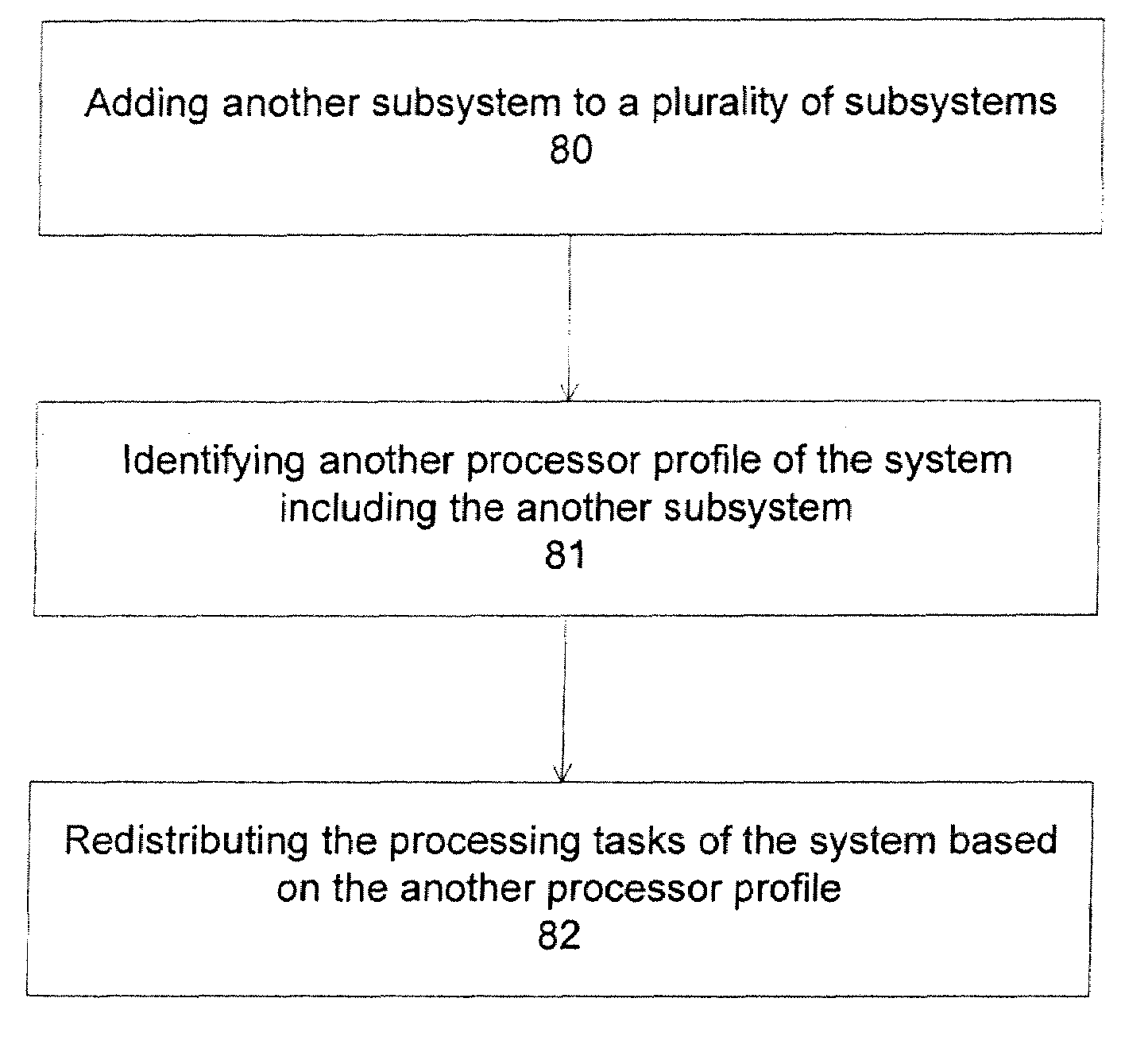
[0009]In one embodiment, a software component, such as a software driver, for a subsystem is provided, which contains the information of power consumption, performance, cost effectiveness for the computational processes that the subsystem is capable of executing. The software driver or other software component allows the adding, upgrading or exchanging subsystems within a data processing system and still effectively provides the capacity for a redistribution of computational processes among the existing subsystems.
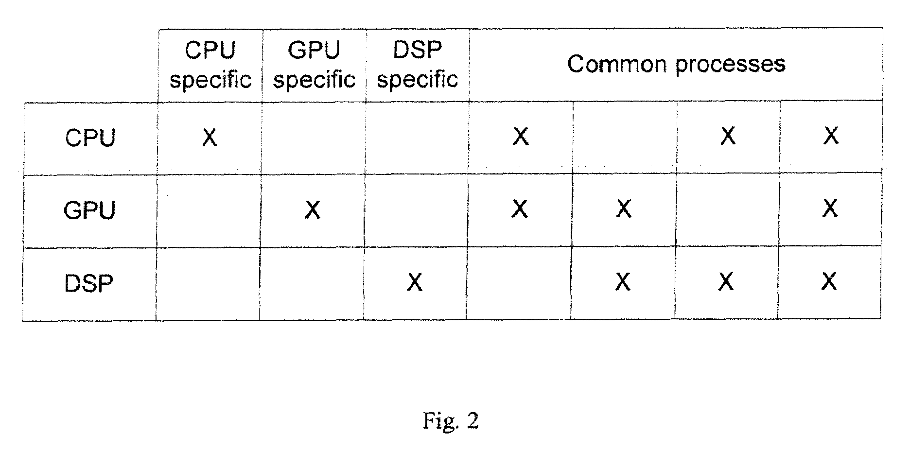
[0011]In one embodiment, the power consumption, the performance or the cost effectiveness of the computational processes are determined for each of the subsystems. This information can be provided through pre-determined matrices, providing the evaluation of the specific computational process to be run in various subsystems. Preferably, the evaluation also considers the loading factor, e.g. how busy the subsystems currently are or the current remaining capacity of the subsystems. The redistributing of computational processes can reduce power consumption without affecting system performance level.

Problems solved by technology

Further, as the operating power consumption of individual components of a typical computer system creep upwards, the power budget of such a system has become tighter.
It is now becoming a challenge to design a computer system to simultaneously achieve various high performance goals, such as high computing power, compactness, quietness, better battery performance, etc.
For example, portable computer systems, such as laptop computers, have a limited battery output capability; and thus a given battery output capability may limit a system from performing at a continuous high performance capability with dedicated processing units for certain computational processes.

Method used


Image

  • Methods and apparatuses for load balancing between multiple processing units
  • Methods and apparatuses for load balancing between multiple processing units
  • Methods and apparatuses for load balancing between multiple processing units

Examples


Embodiment Construction

[0028]The following description and drawings are illustrative of the invention and are not to be construed as limiting the invention. Numerous specific details are described to provide a thorough understanding of the present invention. However, in certain instances, well known or conventional details are not described in order to avoid obscuring the description of the present invention. References to one or an embodiment in the present disclosure are not necessarily references to the same embodiment; and, such references mean at least one.

[0029]Low power consumption is often a desirable goal for current computer systems, especially for portable computer systems, such as laptop computers, which have a limited battery output capability. Other types of data processing systems, such as special purpose computers, cellular telephones, personal digital assistants (PDAs), entertainment systems, media players, embedded systems, and consumer electronic devices, also often require low power co...


PUM


Abstract

Exemplary embodiments of methods and apparatuses to dynamically redistribute computational processes in a system that includes a plurality of processing units are described. The power consumption, the performance, and the power / performance value are determined for various computational processes between a plurality of subsystems where each of the subsystems is capable of performing the computational processes. The computational processes are exemplarily graphics rendering process, image processing process, signal processing process, Bayer decoding process, or video decoding process, which can be performed by a central processing unit, a graphics processing units or a digital signal processing unit. In one embodiment, the distribution of computational processes between capable subsystems is based on a power setting, a performance setting, a dynamic setting or a value setting.

Description

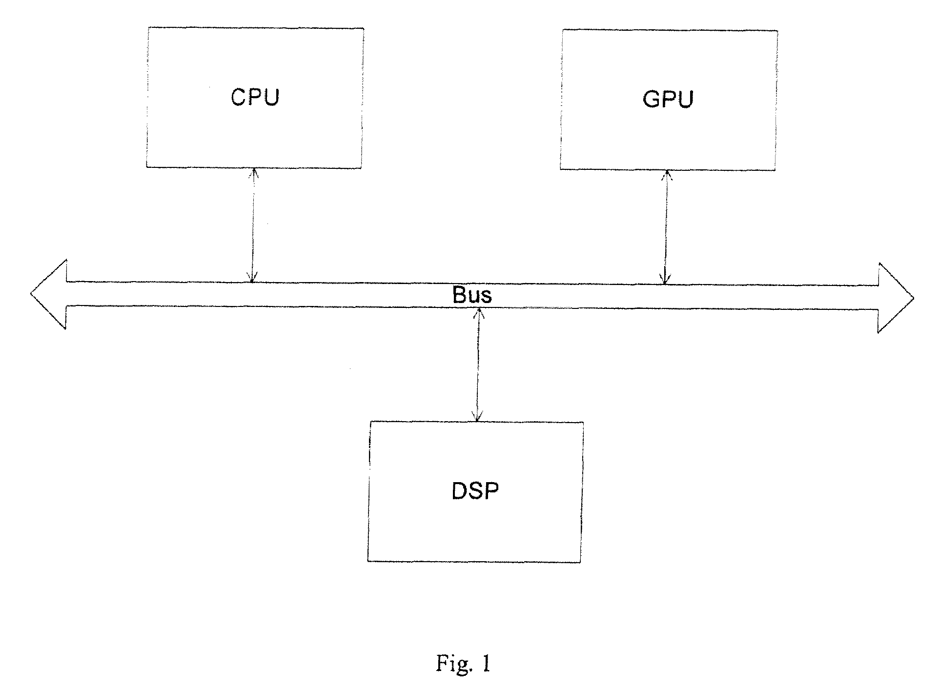
TECHNOLOGY FIELD[0001]At least some embodiments of the present invention relate generally to data processing systems, and more particularly but not exclusively to the management of power usage in data processing systems.BACKGROUND[0002]Traditionally, computer systems are designed to customarily and separately handle different processing tasks. For example, central processing units (CPU) are designed to handle general purpose processes, graphics processing units (GPU) are designed to handle graphics-related processes, and digital signal processing units (DSP) are designed to handle digital signal computational processes.[0003]Further, as the operating power consumption of individual components of a typical computer system creep upwards, the power budget of such a system has become tighter. It is now becoming a challenge to design a computer system to simultaneously achieve various high performance goals, such as high computing power, compactness, quietness, better battery performance...

Claims


Application Information

Patent Timeline
IPC IPC(8): G06F15/16G06T1/20
CPCG06F1/3203G06F1/329G06F9/5044G06F2209/501Y02B60/142Y02B60/144G06F9/5094Y02D10/00G06F15/16
Inventor MILLER, HOWARDBRUNNER, RALPH
Owner APPLE INC
Learn More