Polarity checking apparatus for multi-fiber connectors

Inactive Publication Date: 2009-04-30
CORNING OPTICAL COMM LLC
View PDF14 Cites 16 Cited by
  • Summary
  • Abstract
  • Description
  • Claims
  • Application Information

AI Technical Summary

Benefits of technology

[0006]One embodiment of the present disclosure is directed to a polarity checking apparatus for multi-fiber connectors having a body with a first portion and a second portion. A diverging lens is attached to the first portion of the body and a screen is attached to the second portion of the body. The first portion of the body is configured to mate with a suitable fiber optic connector having a multi-fiber ferrule to test and/or determine polarity of the same. Specifically, the screen includes one or more targets for checking whether a signal is present on a predetermined optical fiber position of the multi-fiber connector. Although, the first portion of the body is configured to mate with the fiber optic connector or multi-fiber ferrule, it preferably avoids contact with a ferrule end face,

Problems solved by technology

Unlike factory-terminated distribution cables, verifying proper polarity of the optical fibers at the field termination of the access location is burdensome and may cause damage to the end face of a ferrule used in the fiber optic connector.
Attaching a compatible connector for testing/polarity checking risks contamination

Method used


Image

  • Polarity checking apparatus for multi-fiber connectors
  • Polarity checking apparatus for multi-fiber connectors
  • Polarity checking apparatus for multi-fiber connectors

Examples


Embodiment Construction

[0015]The present disclosure will now be described more fully hereinafter with reference to the accompanying drawings in which exemplary embodiments of the disclosure are shown. However, aspects of this disclosure may be embodied in many different forms and should not be construed as limited to the embodiments set forth herein. These exemplary embodiments are provided so that this disclosure will be both thorough and complete, and will fully convey the scope of the disclosure to those skilled in the art. Whenever possible, like reference numerals will be used throughout the detailed description of the disclosure to refer to like or similar elements of the various drawings.

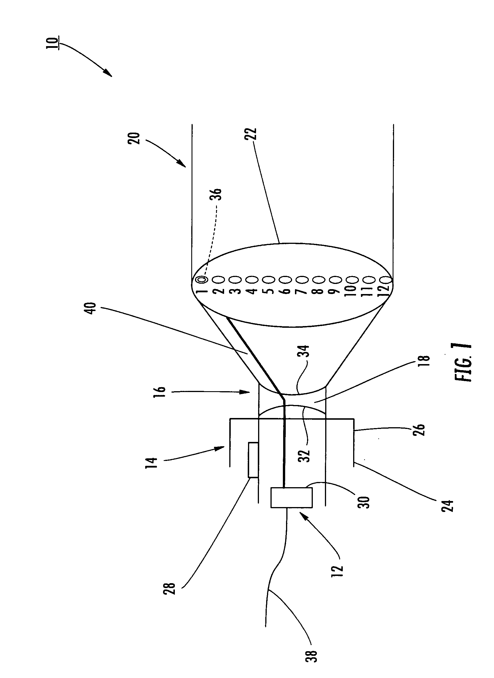
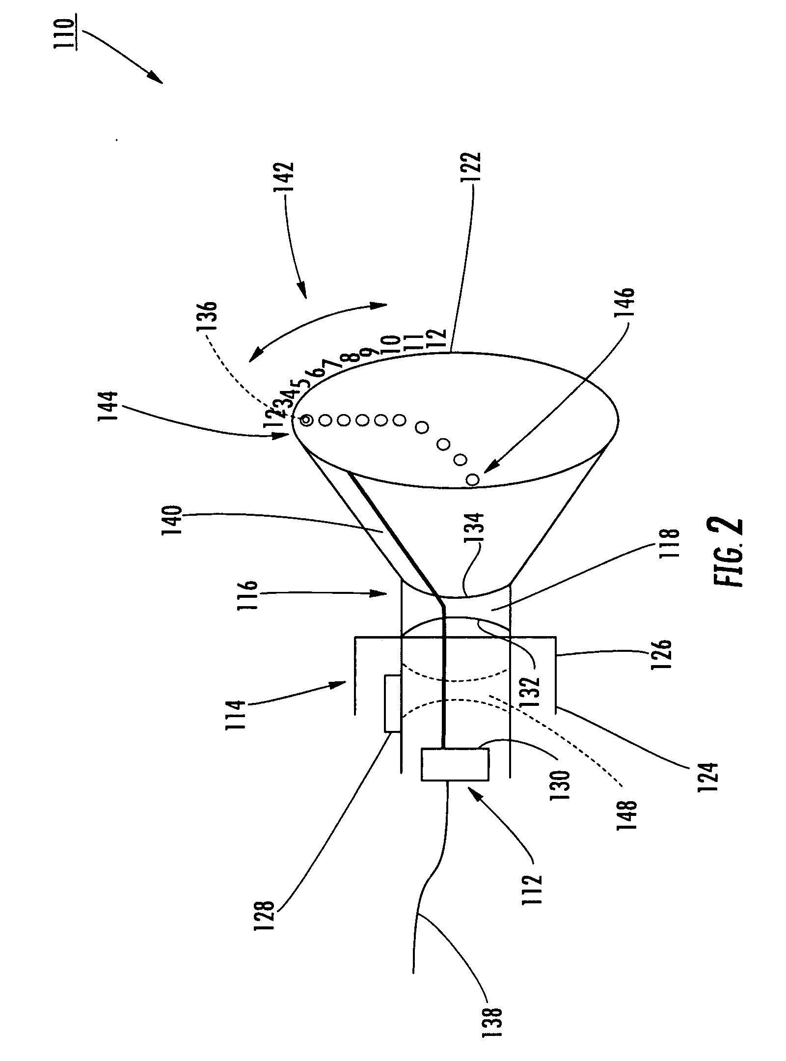
[0016]The present disclosure generally provides various embodiments of a polarity checking apparatus for determining whether a signal is carried by an optical fiber of a multi-fiber array connector. The polarity checking apparatus is advantageous because it minimizes risk of damage by eliminating any need to contac...


PUM


Abstract

A polarity checking apparatus for multi-fiber connectors includes a body, a diverging lens attached to the body and a screen attached to the body, wherein the apparatus is configured to determine test and/or determine polarity of the multi-fiber connector. The screen may be translucent or may be opaque in part and rotatable for checking whether a signal is being transmitted on an individual optical fiber position of the multi-fiber connector. The invention is also directed to a method for checking the polarity of an optical assembly.

Description

BACKGROUND OF THE INVENTION[0001]Service providers are building communications networks that push optical fibers closer to subscribers, thereby increasing the bandwidth and reliability for the subscribers. This build-out of the optical network uses fiber optic distribution cables to route optical fibers toward the subscribers. Fiber optic distribution cables have access locations that are selected and accessed along the distribution cable for routing one or more optical fibers away from the distribution cable and toward the subscriber. For instance, some distribution cables are factory-terminated at, or near, the access locations with multi-fiber optic connectors. However, in many cases, distribution cables are field-terminated such as by fusion splicing of factory-terminated assemblies at the desired access location.[0002]Unlike factory-terminated distribution cables, verifying proper polarity of the optical fibers at the field termination of the access location is burdensome and m...

Claims


Application Information

Patent Timeline
IPC IPC(8): G01N21/00
CPCG02B6/403G02B6/262
Inventor BURNETT, JULIE A.CONNER, MARK E.QUINBY, ERIC S.
Owner CORNING OPTICAL COMM LLC
Why Eureka
Try Eureka