Optical Assembly for Repetitive Coupling and Uncoupling

a technology of optical assembly and coupling, applied in the field of optical assembly, can solve the problems of many precision component parts, contamination and condensation of particulates, and the practice of a single precision component is encountered in the field of practi

Active Publication Date: 2009-04-30
CINCH CONNECTORS
View PDF76 Cites 66 Cited by
  • Summary
  • Abstract
  • Description
  • Claims
  • Application Information

AI Technical Summary

Benefits of technology

[0006]An object of the present invention is to provide an optical assembly which is operable to provide a collimated beam of radiation and which requires fewer precision components in its manufacture and yet allows for repetitive coupling and uncoupling of its associated optical fiber.

Problems solved by technology

Such a relatively small outside diameter of the optical cores renders such fibers, especially monomode fibers having a core diameter of substantially 9 micrometers, potentially difficult to mutually align and thereby represents a problem in ensuring efficient coupling of optical energy therebetween.
Although such coupling can be achieved by the use of precision zirconium ferrules to mutually precision abut fibers, practical problems are encountered in practice, especially regarding particulate contamination and condensation.
However, the optical connection employs many precision component parts and only caters for adjustment of a distance between the spherical lenses, namely an axial length of the radiation propagation region provided between the spherical lenses.
The optical connection is thereby potentially costly to manufacture on account of a relatively large number of precision parts being required to be precision manufactured and thereafter mutually assembled.
The optical connection is unsuitable for coupling monomode fibers together, such fibers have an optical core diameter in the order of 9 micrometers, on account of excessive precision to which component parts of the optical connection would have to be manufactured.
Thus, the aforementioned expanded beam connector system does not allow for decoupling of its optical fibers from their respective lenses in use, and the optical connection is complex and potentially costly to manufacture on account of precision components being required for its manufacture.

Method used


Image

  • Optical Assembly for Repetitive Coupling and Uncoupling
  • Optical Assembly for Repetitive Coupling and Uncoupling
  • Optical Assembly for Repetitive Coupling and Uncoupling

Examples


Embodiment Construction

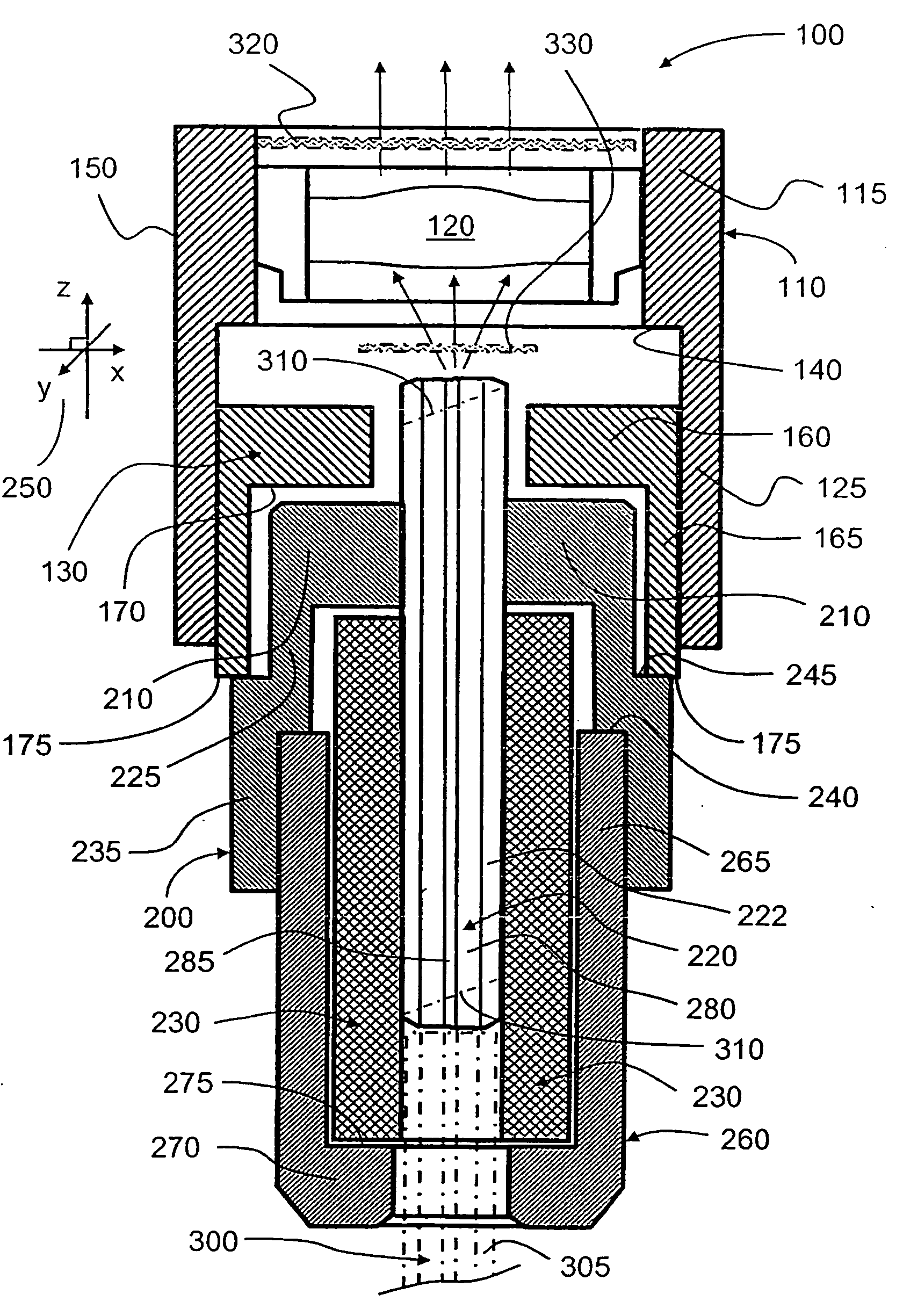
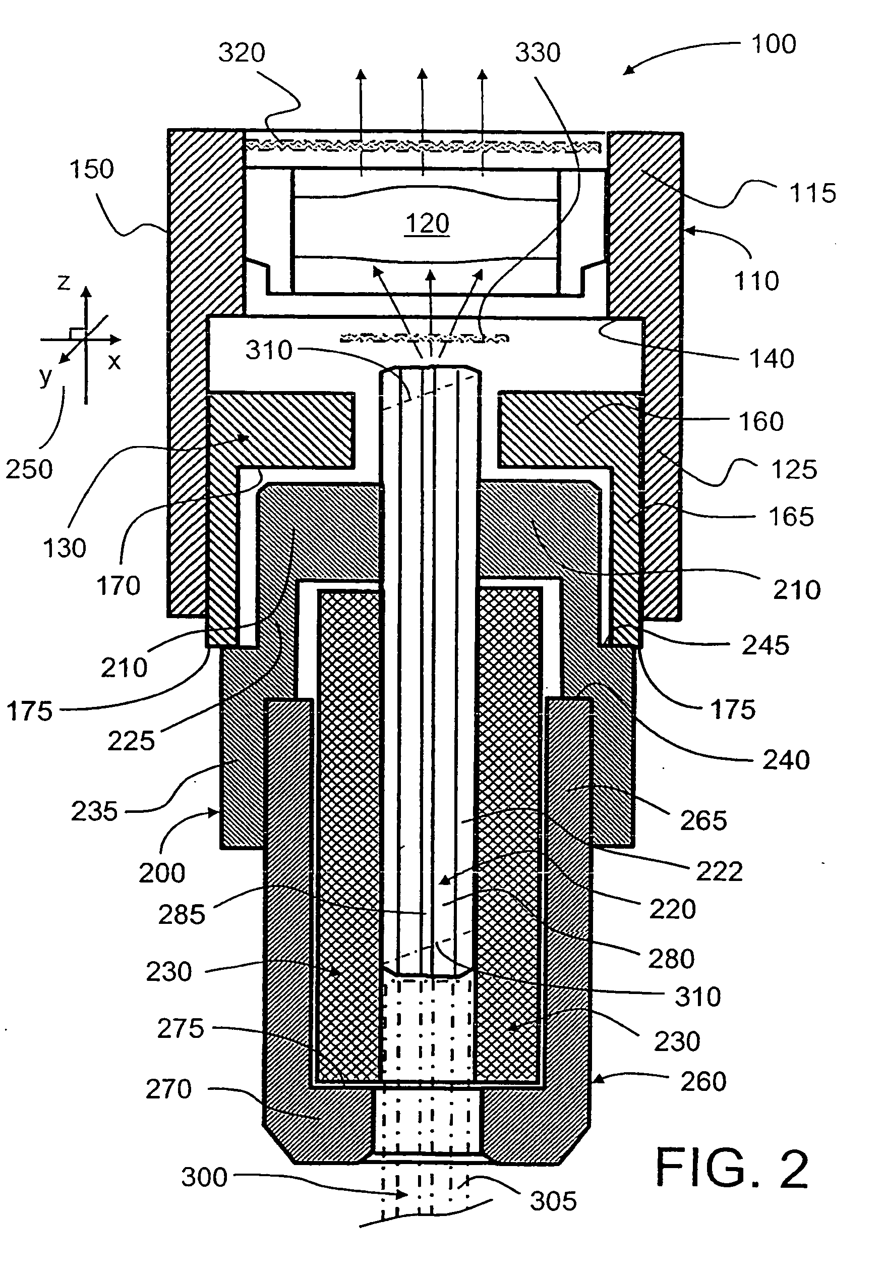
[0052]An embodiment of an optical assembly according to the present invention is illustrated in FIG. 2, the assembly being indicated generally by 100 and being also known as an Expanded Beam Optical Sub Assembly (EBOSA). The assembly (EBOSA) 100 is capable of being employed to implement an expanded beam connector, and also to implement a free-air communication link capable of being used in field situations where precision alignment apparatus is not available. The assembly 100 comprises an outer lens holder 110 of substantially tubular form, the lens holder 110 having a first portion 115 with relatively thicker wall for receiving a lens 120 therein, and a second portion 125 with relatively thinner wall for receiving a z-axis alignment sleeve 130. A step transition 140 is provided on an inner surface of the lens holder 110, the step transition 140 distinguishing the first portion 115 from the second portion 125. The step transition 140 is also capable of preventing the z-axis alignmen...


PUM


Abstract

There is provided an optical assembly (100) comprising an optical fiber arrangement (220, 230) and a lens arrangement (120). The lens arrangement (120) is spatially disposed relative to the fiber arrangement (220, 230) so as to be capable of providing an axial substantially collimated beam of radiation in response to receiving radiation from the optical fiber arrangement (220, 230) and capable of providing a focused beam of radiation to the optical fiber arrangement (220, 330) in response to receiving substantially collimated radiation to the lens arrangement (120). The assembly (100) further comprises a configuration of elements (110, 130, 200, 260) for spatially disposing the optical fiber arrangement (220, 230) relative to the lens arrangement (120). The configuration of elements (110, 130, 200, 260) provides for independent adjustment of relative lateral position between the optical fiber arrangement (220, 230) and the lens arrangement (120) in relation to axial position of the optical fiber arrangement (220, 230) relative to the lens arrangement (120). Such independent adjustment assists in fabrication of the assembly (100).

Description

FIELD OF THE INVENTION[0001]The present invention relates to optical assemblies, for example to optical assemblies for coupling optical fibers together and connecting optical fibers to data apparatus. Moreover, the present invention also relates to methods of manufacturing such optical assemblies. Furthermore, the invention relates to couplers and apparatus including such optical assemblies.BACKGROUND TO THE INVENTION[0002]It is known that contemporary optical fibers have relatively small optical cores often only a few micrometers in outer diameter, and an outer optical cladding having a diameter in an order of hundreds of micrometers in outer diameter, a refractive index difference between the optical cores and their corresponding optical claddings providing such contemporary optical fibers with light-guiding properties for conveying optical radiation bearing information therealong. Such light-guiding properties are employed widely within modern telecommunication systems. Such a re...

Claims


Application Information

Patent Timeline
Patent Type & Authority Applications(United States)
IPC IPC(8): G02B6/26G02B6/38G02B6/32
CPCG02B6/32G02B6/3504G02B6/381G02B6/3874G02B6/3877G02B6/327G02B6/3846G02B6/3853G02B6/3878
Inventor JACOBSSON, CLAES
Owner CINCH CONNECTORS
Why Eureka
Try Eureka