Alumina-based protective coatings for thermal barrier coatings

a technology of alumina-based protective coatings and thermal barrier coatings, which is applied in the direction of superimposed coating process, natural mineral layered products, transportation and packaging, etc., can solve the problems of unintentional interference with the desired spallation resistance, affecting other properties of thermal barrier coatings, and still susceptible to various types of damage, etc., to achieve the effect of increasing the melting poin

Active Publication Date: 2009-04-30
GENERAL ELECTRIC CO
View PDF15 Cites 27 Cited by
  • Summary
  • Abstract
  • Description
  • Claims
  • Application Information

AI Technical Summary

Benefits of technology

[0012]Disclosed herein are processes and coating systems for mitigating CMAS and providing anti-fouling protection to a thermal barrier coating disposed on metallic components. In one embodiment, a process for depositing an alumina-based coating onto a thermal barrier coating comprises providing an article with a thermal barrier coating disposed thereon; heating an alumina powder, wherein the alumina powder has a composition of at least 60 weight percent alumina with a balance comprising titania, zirconia, and gadolinia; and thermally spraying the alumina powder onto the thermal barrier coating to form the alumina-based coating, wherein the alumina-based coating increases a melting point of a contaminant composition comprising mixed calcium-magnesium-aluminum-silicon-oxides relative to the contaminant composition in the absence of the alumina-based coating.

Problems solved by technology

Although significant advances have been made in improving the durability of thermal barrier coatings for turbine engine components, such coatings are still susceptible to various types of damage, including objects ingested by the engine, erosion, oxidation, and attack from environmental contaminants.
In addition, in trying to achieve reduced thermal conductivity, other properties of the thermal barrier coating can be adversely impacted.
However, such modifications can also unintentionally interfere with desired spallation resistance, especially at the higher temperatures that most turbine components are subjected to.
As a result, the thermal barrier coating can become more susceptible to damage due to the impact of, for example, objects and debris ingested by the engine and passing through the turbine sections thereof.
Such impact damage can eventually cause spallation and loss of the thermal barrier coating.
In addition, at the higher temperatures of engine operation, the environmental contaminants can adhere to the heated or hot thermal barrier coating and subsequently cause damage.
Upon cooling, the infiltrated contaminants solidify and reduce the coating strain tolerance, thus initiating and propagating cracks that cause delamination, spalling and loss of the thermal barrier coating material either in whole or in part.
Damage may also result from the freezing contaminants having a different coefficient of thermal expansion relative to the TBC.
These pores, channels or other cavities that are infiltrated by such molten environmental contaminants can be created by environmental damage, or even the normal wear and tear that results during the operation of the engine.
Damage to the TBC typically occurs when the molten CMAS infiltrates the porous surface structure of the thermal barrier coating.
This solidified CMAS causes stresses to build within the thermal barrier coating, leading to partial or complete delamination and spalling of the coating material and, thus partial or complete loss of the thermal protection provided to the underlying metal substrate of the part or component.
Without CMAS mitigation, the TBC is often compromised and the component could fail before it next service interval.
However, CVD processes are prohibitively expensive and slow.
The CVD process does not lend its self to the large scale of gas turbine components since it requires controlled atmospheric conditions.
With regard to the use of alcohol based slurry solutions, these solutions generally provide a limited shelf life, high cost and are typically incorporate hazardous organic solvents.
The slurry coatings are not practical for CMAS mitigation because the thicknesses of the coatings are limited.
Moreover, with regard to anti-fouling applications, the cohesive strength of the slurry coating is limited because it cannot be sintered without melting the metallic component to which it is applied.
Another limitation of the current slurry process is that it is limited to service temperatures of 2000° F. making it incompatible with the CMAS environment.
Moreover, current slurry methods also generally require a 12 hour dry followed by 8 hour high temperature cure, making manufacturing costs high.

Method used


Image

  • Alumina-based protective coatings for thermal barrier coatings
  • Alumina-based protective coatings for thermal barrier coatings

Examples


Embodiment Construction

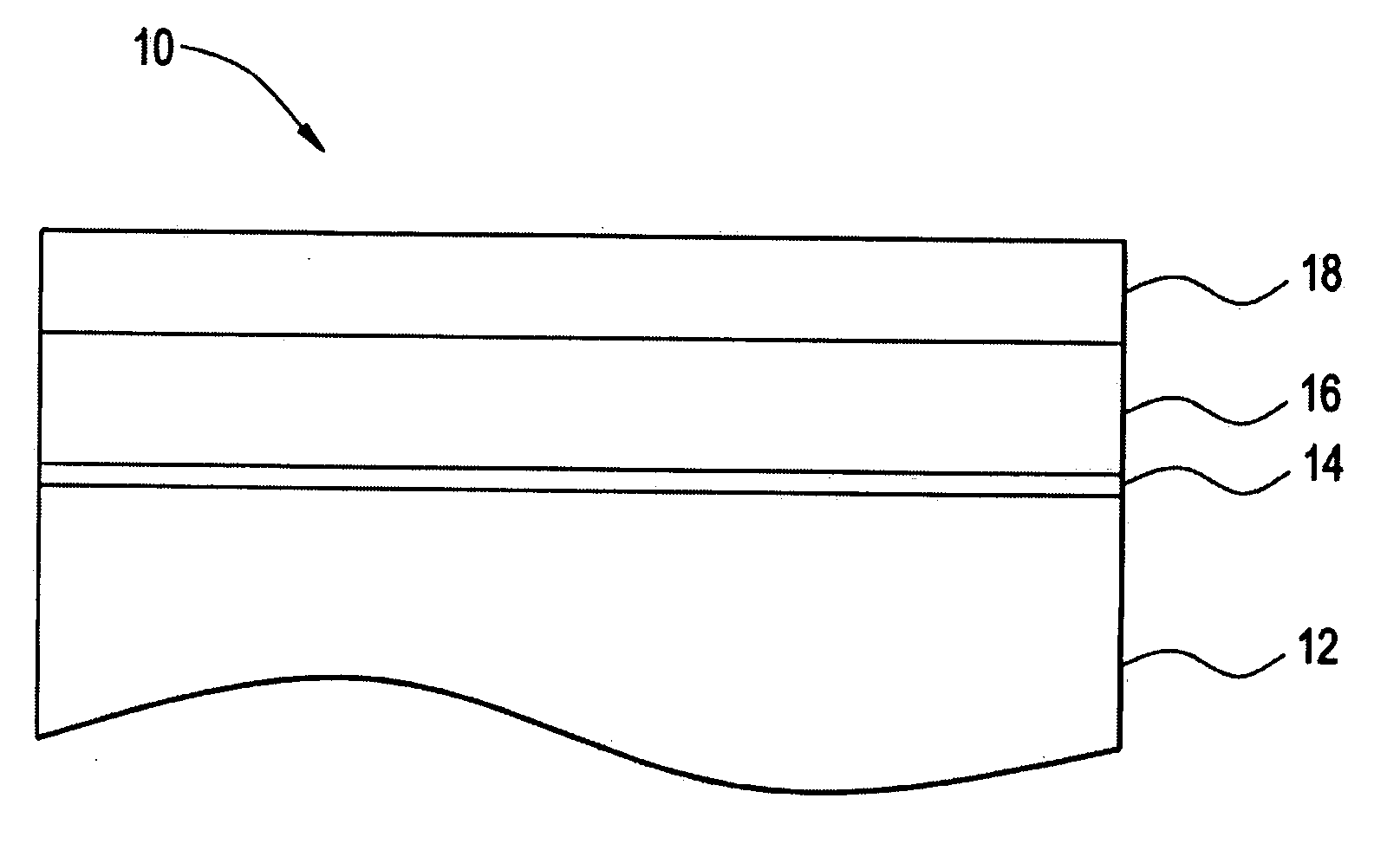
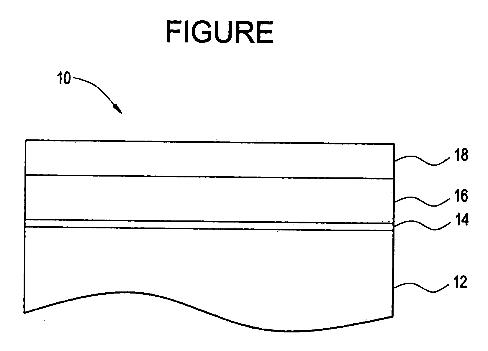
[0016]Disclosed herein are methods for mitigating CMAS and providing anti-fouling protection to a thermal barrier coating (TBC) disposed on metallic components, e.g., gas turbine components. The process generally includes thermally spraying an alumina-based layer of onto the TBC. As used herein, the terms “alumina” and “aluminum oxide” refer interchangeably to those compounds and compositions comprising Al2O3, including, but not limited to, the unhydrated and hydrated forms. As will be described herein, the proposed coating could protect the TBC at temperatures up to about 3000° F. Moreover, in contrast to the prior methods, the application method can be completed within in minutes, without the need for drying or curing.

[0017]In one embodiment, a thermally sprayed alumina-based coating is applied to the TBC, which chemically elevates the CMAS melting point. Advantageously, the resulting thermally sprayed coating is substantially smooth so as to reduce fouling. The method for deposit...


PUM

PropertyMeasurementUnit
surface roughnessaaaaaaaaaa
thicknessaaaaaaaaaa
temperatureaaaaaaaaaa

Abstract

A thermally sprayed alumina-based coating is deposited onto a thermal barrier coating to provide an article such as a turbine engine component with both CMAS mitigation and antifouling. The alumina-based coating increases a melting point of the CMAS to a temperature greater than an operating temperature of the turbine engine component. The surface roughness of the thermally sprayed alumina based coating in less than 4.0 micrometers to 0.75 micrometers. The alumina based coatings include at least 60 weight percent alumina based on a total weight of the alumina-based coating.

Description

BACKGROUND OF THE INVENTION[0001]The present disclosure generally relates to alumina protective coatings for thermal barrier coatings, and more specifically, thermally sprayed alumina-based protective coatings for thermal barrier coatings utilized in various surfaces on gas turbine components.[0002]In turbine engines, such as but not limited to aircraft and power generation turbines, air is drawn into the front of the engine, compressed by a shaft-mounted compressor, and mixed with fuel. The air-fuel mixture is combusted, and the resulting hot combustion gas is passed through a turbine mounted on the same shaft. The turbine includes a rotor with turbine blades supported on its periphery, and a stationary (that is, not rotating) gas turbine flow path shroud that confines the combustion gas to flow through the annulus between the rotor and the shroud, and thence against the turbine blades. The constrained flow of hot combustion gas turns the turbine by contacting an airfoil portion of...

Claims


Application Information

Patent Timeline
Patent Type & Authority Applications(United States)
IPC IPC(8): B32B3/26B05D1/02B32B15/04
CPCC23C4/02C23C4/105C23C4/18C23C28/3455C23C28/3215C23C28/345Y02T50/67C23C4/10C23C28/04C23C28/042C23C4/11Y10T428/249953Y10T428/31678Y02T50/60
Inventor MARGOLIES, JOSHUA L.
Owner GENERAL ELECTRIC CO
Why Eureka
Try Eureka