
Skeletal manipulation system

a technology of manipulating system and skeletal system, which is applied in the field of medical devices for treating disorders of the skeletal system, can solve the problems of actual creation of noticeable deformation, rapid and severe curve progress, and difficulty in clinical trials of staples

Inactive Publication Date: 2009-04-30
ELLIPSE TECH
View PDF99 Cites 132 Cited by
  • Summary
  • Abstract
  • Description
  • Claims
  • Application Information

AI Technical Summary

Benefits of technology

[0012]In another embodiment, a system for manipulating a portion of the skeletal system in the body of a subject includes an implant having a first portion and a second portion, the first portion configured for placement on the skeletal system of the subject at a first location and the second portion configured for placement on the skeletal system of the subject at a second location. The system includes an adjustment device disposed on the implant and having a magnetic element with a mass of three grams or less configured for rotation about an axis of rotation,

Problems solved by technology

In more severe cases, this rotation actually creates a noticeable deformity, wherein one shoulder is lower than the other.
Many school districts do not perform this assessment, and many children do not regularly visit a physician, so often, the curve progresses rapidly and severely.
Many of these adults, though, do not have pain associated with this deformity, and live relatively normal lives, though oftentimes with restricted mobility and motion.
The staples have had some difficulty in the clinical trials.
Once the patient reaches spinal maturity, it is difficult to remove the rods and associated hardware in a subsequent surgery, because the fusion of the vertebra usually incorporates the rods themselves.
With either of these two surgical methods, after fusion, the patient's spine is now straight, but depending on how many vertebra were fused, there are often limitations in the degree of flexibility, both in bending and twisting.
As these fused patients mature, the fused section can impart large stresses on the adjacent non-fused vertebra, and often, other problems including pain can occur in these areas, sometimes necessitating further surgery.
Because the patients may receive the device at an age as early as six months old, this treatment requires a large number of surgeries.
Returning to the AIS patients, the treatment methodology for those with a Cobb angle between 20° and 40° is quite controversial.
Because these patients are all passing through their socially demanding adolescent years, it is quite a serious prospect to be forced with the choice of either wearing a somewhat bulky brace that covers most of the upper body, having fusion surgery that may leave large scars and also limit motion, or doing nothing and running the risk of becoming disfigured and possibly disabled.
The patient compliance with brace wearing has been so problematic, that there have been special braces constructed which sense the body of the patient, and keep track of the amount of time per day that the brace is worn.
Coupled with the inconsistent patient compliance with brace usage, is a feeling by many physicians that braces, even if used properly, are not at all effective at curing scoliosis.
These physicians may agree that bracing can possibly slow down or even temporarily stop curve (Cobb angle) progression, but they have noted that as soon as the treatment period ends and the brace is no longer worn, often the scoliosis rapidly progresses, to a Cobb angle even more severe than it was at the beginning of treatment.
Some say the reason for the supposed ineffectiveness of the brace is that it works only on a portion of the torso, and not on the entire spine.
Many physicians feel that the BrAIST trial will show that braces are completely ineffective.
Once identified, some are still skeptical as to whether gene therapy would be possible to prevent scoliosis, however the existence of a scoliosis gene would no doubt allow for easier and earlier identification of probable surgical patients.

Method used


Image

  • Skeletal manipulation system
  • Skeletal manipulation system
  • Skeletal manipulation system

Examples


Embodiment Construction

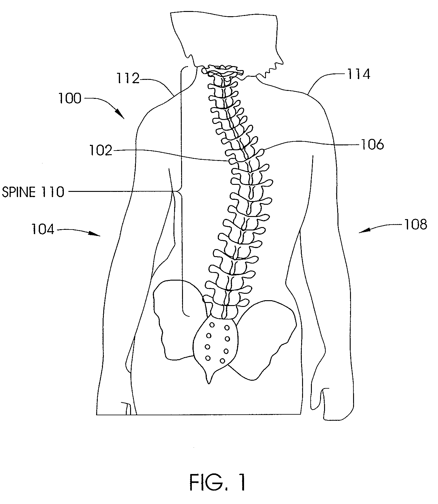
[0071]FIG. 1 illustrates a patient 100 with scoliosis. The concave portion 102 of the spinal curve can be seen on the left side 104 of the patient 100, and the convex portion 106 can be seen on the right side 108 of the patient 100. Of course, in other patients, the concave portion 102 may appear on the right side 108 of the patient 100 while the convex portion 106 may be found on the left side 104 of the patient. In addition, as seen in FIG. 1, some rotation of the spine 110 is present, and unevenness between the left shoulder 112 and right shoulder 114 is seen.

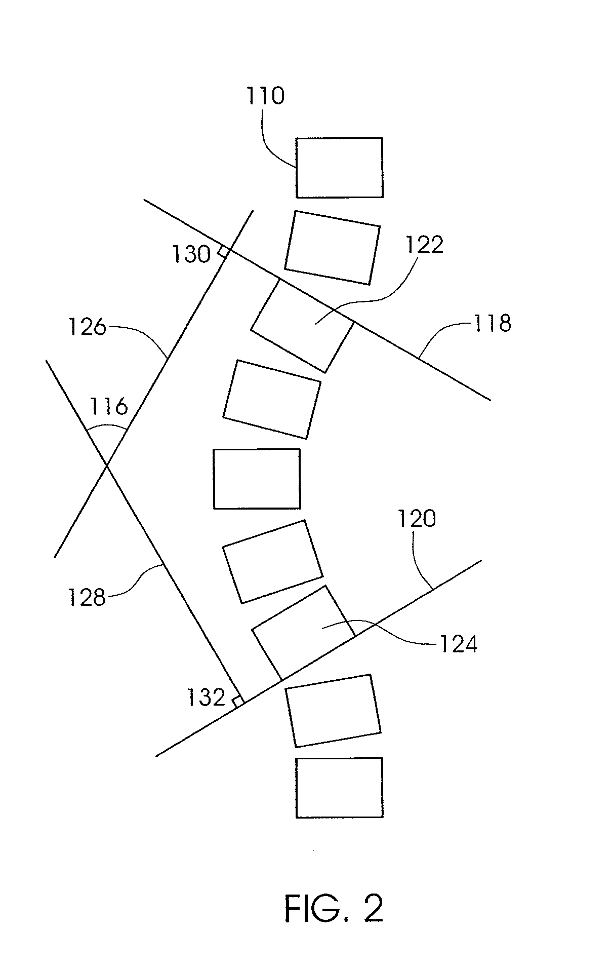
[0072]FIG. 2 illustrates the Cobb angle 116 of a spine 110 of a patient with scoliosis. To determine the Cobb angle, lines 118 and 120 are drawn from vertebra 122 and 124, respectively. Intersecting perpendicular lines 126 and 128 are drawn by creating 90° angles 130 and 132 from lines 118 and 120. The angle 116 created from the crossing of the perpendicular lines 126 and 128 is defined as the Cobb angle. In a perfectly stra...


PUM


Abstract

A system for manipulating a portion of the skeletal system in the body of a mammal includes an implant having a first portion and a second portion, the first portion configured for coupling to a first location of the skeletal system and the second portion configured for coupling to a second location of the skeletal system. The system includes an adjustment device configured to change at least one of the distance or force between the first location and the second location, the adjustment device having a magnetic element configured for rotation about an axis of rotation, the magnetic element being operatively coupled to a drive element configured to alter at least one of the distance or the force between the first location and the second location. The system also includes an external adjustment device configured to magnetically couple to the adjustment device from a location external to the mammal.

Description

RELATED APPLICATION[0001]This Application claims priority to U.S. Provisional Patent Application No. 60 / 983,917 filed on Oct. 30, 2007. The '917 Provisional Patent Application incorporated by reference as if set forth fully herein.FIELD OF THE INVENTION[0002]The field of the invention generally relates to medical devices for treating disorders of the skeletal system.BACKGROUND OF THE INVENTION[0003]Scoliosis is a general term for the sideways (lateral) curving of the spine, usually in the thoracic or thoracolumbar region. Scoliosis is commonly broken up into different treatment groups, Adolescent Idiopathic Scoliosis, Early Onset Scoliosis and Adult Scoliosis. Adolescent Idiopathic Scoliosis (AIS) typically affects children between ages 10 and 16, and becomes most severe during growth spurts that occur as the body is developing. One to two percent of children between ages 10 and 16 have some amount of scoliosis. Of every 1000 children, two to five develop curves that are serious eno...

Claims


Application Information

Patent Timeline
IPC IPC(8): A61B17/70A61H1/00
CPCA61B17/7016A61B17/7044A61B17/7065A61B17/707A61B17/88A61B17/7266A61B17/8004A61B2017/00411A61B17/68A61B17/7216A61B17/8866A61B2017/00876A61B2017/564A61B2017/681
Inventor POOL, SCOTTCHANG, ARVINWALKER, BLAIRTRAN, PETER P.MCCOY, JAY R.
Owner ELLIPSE TECH
Learn More